PSV5000_OwnersManual.pdf - 第50页
Setup ■ S etting Up In put and Output Media - 46 - Data I/O ■ 096 - 0465 - 00 1C Refer to the following figure for Tray Feeder connections. Figure 23: The Tray Feed er mounting screws (a rrows). Ther e are also tw o fast…
■ Setting Up Input and Output Media □ Setting Up an Automatic Tray Feeder
PSV5000 Owner’s Manual - 45 -
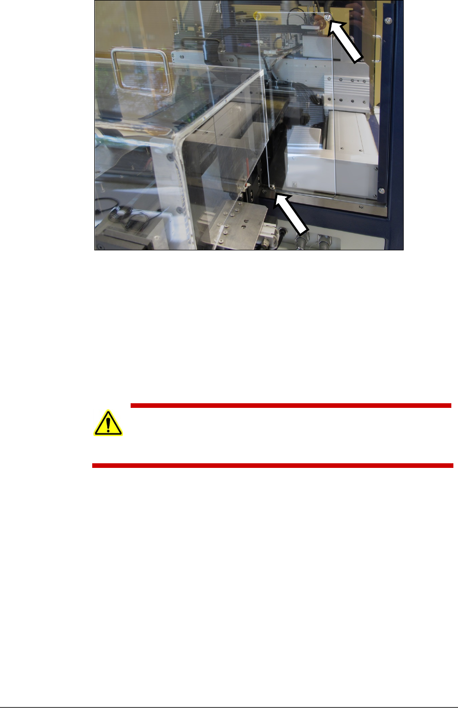
Figure 22: The safety shield for the Tray Feeder has been rotated
out of the way and fastened in the ‘storage’ position with the two
screws (arrows).
4. Loosen the lower right screw.
5. Rotate the shield up 90° clockwise and fasten in place at the extra
hole with the screw removed earlier.
6. Get the Tray Feeder fasteners ready, and a 5 mm hex key.
CAUTION: Heavy equipment! The Tray Feeder weighs 30 kg (66 lb.).
Two people are required to lift it. A third person is needed to attach
fasteners. Use caution.
7. With two people lifting the Tray Feeder, slide the nose into the shield
opening and far enough in to accommodate the mounting holes on
the machine base plate.
Setup ■ Setting Up Input and Output Media
- 46 - Data I/O ■ 096-0465-001C
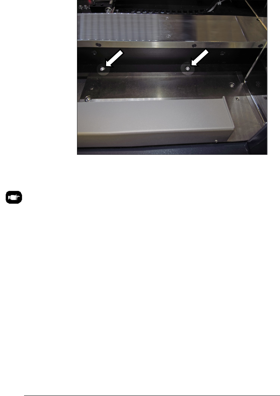
Refer to the following
figure for Tray Feeder
connections.
Figure 23: The Tray Feeder mounting screws (arrows). There are
also two fasteners on the back side of the feeder (not shown).
8. Screw in a screw into each of the four mounting holes to secure the
feeder (5 mm hex key).
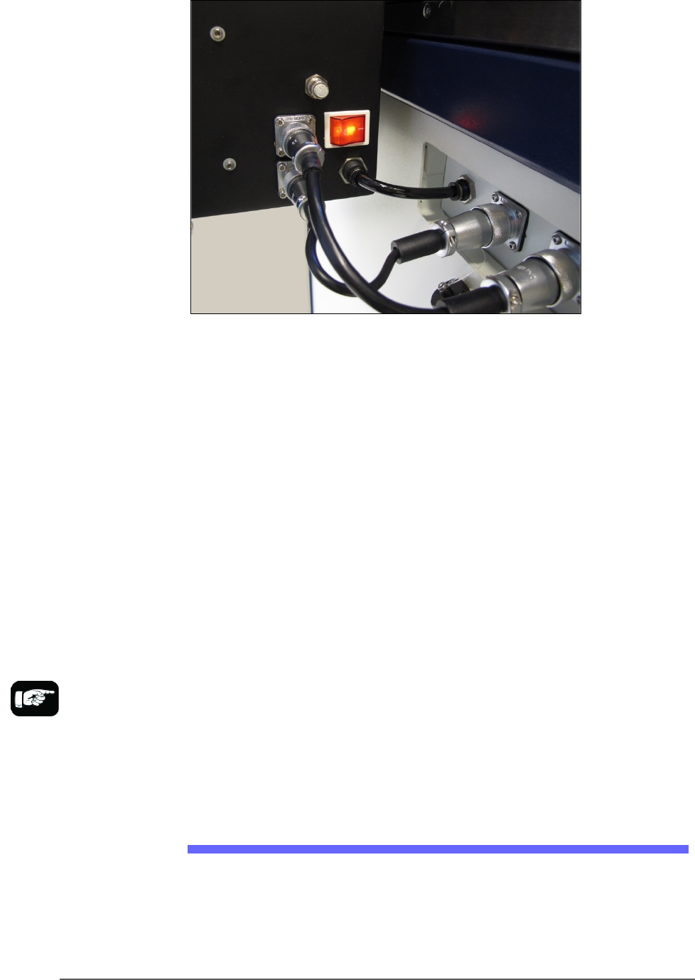
9. Plug in the three utilities: air, electrical, signal cable.
The air connection has One-Touch fittings.
The electrical connector can be rotated until it slides into the socket,
and then screw the knurled ring up.
■ Setting Up Input and Output Media □ The Tape Output Setup and Operation
PSV5000 Owner’s Manual - 47 -
Figure 24: Connection for the Tray Feeder: air, electrical and signal
(left to right).
Very basic operating instructions are covered in the PSV5000 Operators
Manual. Complete instructions are covered in the Tray Feeder Manual.
TRAY ARRANGEMENTS
You can use a spare tray with an Automatic Tray Feeder (ATF). When a
spare static tray is designated, the devices from that spare tray are used
to replace rejected devices. They are also used during a tray change.
Either a reject tray or bin is also required.
Remember that:
• the Setup window > Options tab must be set to match the
workspace setup (covered in the Operator’s Manual).
• The Package File must be taught the location of the reject
container (covered in Chapter 3 of this manual).
• (Optional) If the Sort-On-Error-Code is used, two Reject Bins are
required. Set up for Sort-On-Error-Code by installing a second
reject bin.
The Tape Output Setup and Operation
The PSV5000 System can be configured with an optional Tape Output
System.
The Tape Output System receives programmed devices directly from the
PSV5000 System via the PNP head. The Tape Output System advances
For more about
Sort-On-Error-Code, see
Monitoring Statistics on
page 71.