PSV5000_OwnersManual.pdf - 第52页
Setup ■ S etting Up In put and Output Media - 48 - Data I/O ■ 096 - 0465 - 00 1C the carr ier tape through a mechanism t hat seals the tape (usin g heat or pressure), and rolls the f illed tape onto a reel f or deliver y…
■ Setting Up Input and Output Media □ The Tape Output Setup and Operation
PSV5000 Owner’s Manual - 47 -
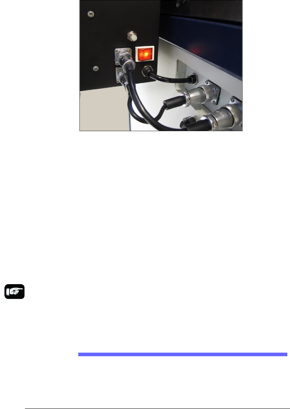
Figure 24: Connection for the Tray Feeder: air, electrical and signal
(left to right).
Very basic operating instructions are covered in the PSV5000 Operators
Manual. Complete instructions are covered in the Tray Feeder Manual.
TRAY ARRANGEMENTS
You can use a spare tray with an Automatic Tray Feeder (ATF). When a
spare static tray is designated, the devices from that spare tray are used
to replace rejected devices. They are also used during a tray change.
Either a reject tray or bin is also required.
Remember that:
• the Setup window > Options tab must be set to match the
workspace setup (covered in the Operator’s Manual).
• The Package File must be taught the location of the reject
container (covered in Chapter 3 of this manual).
• (Optional) If the Sort-On-Error-Code is used, two Reject Bins are
required. Set up for Sort-On-Error-Code by installing a second
reject bin.
The Tape Output Setup and Operation
The PSV5000 System can be configured with an optional Tape Output
System.
The Tape Output System receives programmed devices directly from the
PSV5000 System via the PNP head. The Tape Output System advances
For more about
Sort-On-Error-Code, see
Monitoring Statistics on
page 71.
Setup ■ Setting Up Input and Output Media
- 48 - Data I/O ■ 096-0465-001C
the carrier tape through a mechanism that seals the tape (using heat or
pressure), and rolls the filled tape onto a reel for delivery to the next
stage in the manufacturing process.
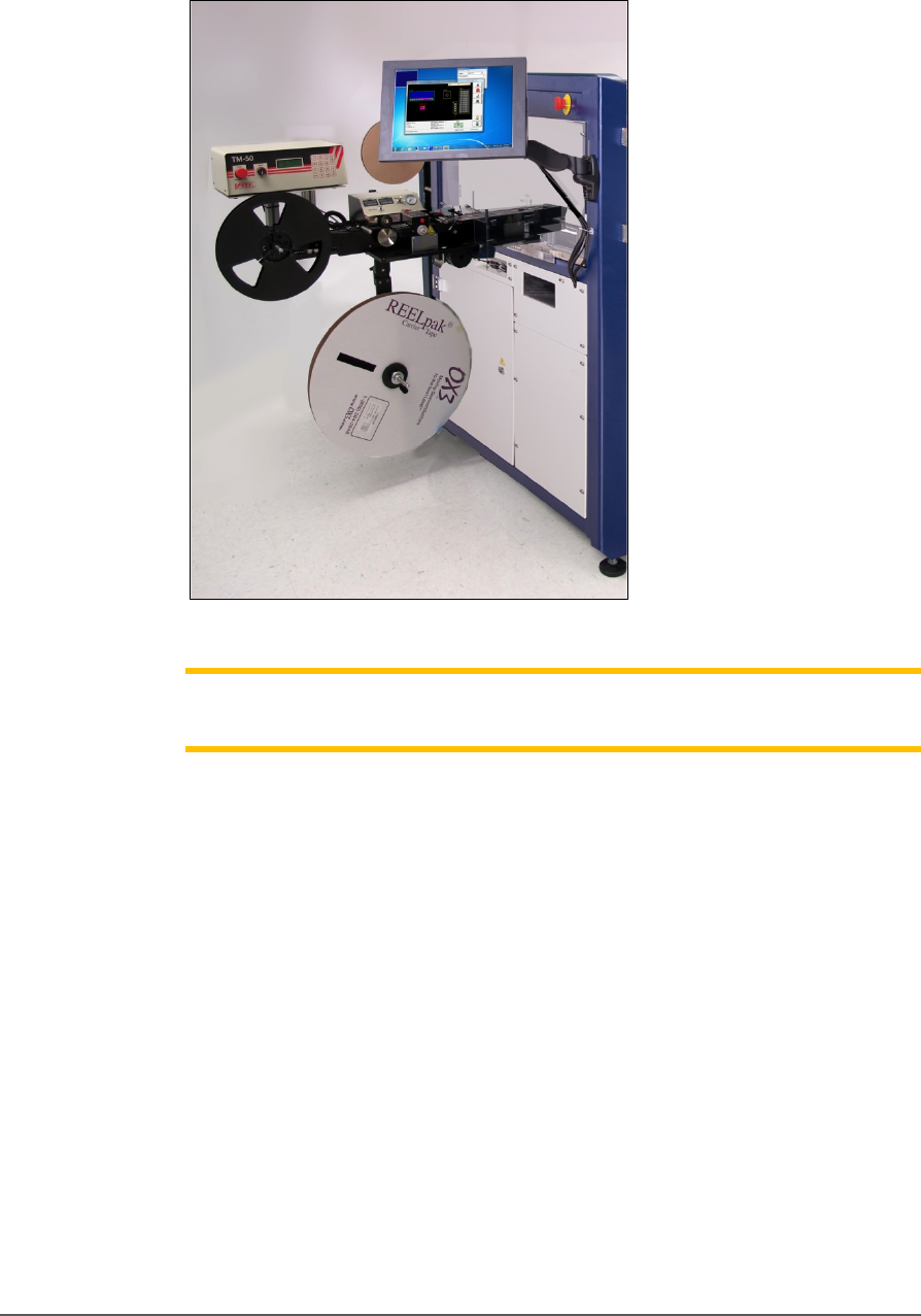
Figure 25: Tape Output Module on PSV5000
Note: For additional information, refer to the TM-50 Tape Output System
User’s Guide that came with your Tape Output System.
INSTALLING THE TAPE OUTPUT MODULE
TOOLS REQUIRED
• Metric hex key set
• Three people to lift / install the Tape Output Module
These steps are for installing the Tape Output Module (which can be
ordered with the PSV5000).
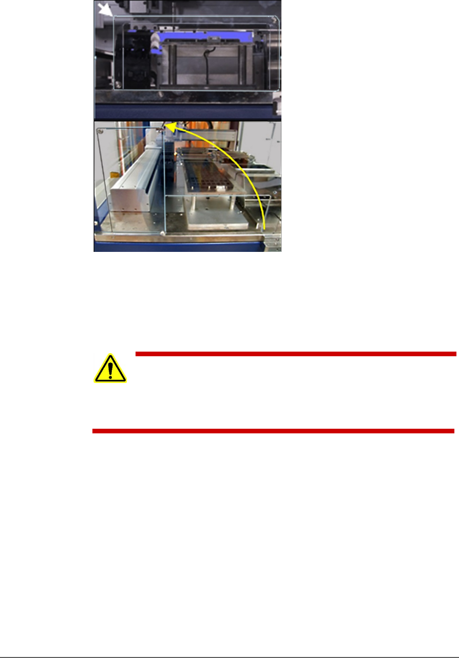
1. On the left side of the machine prepare the small clear safety covers
for receiving the Tape Output Module.
a. Loosen the screw on the lower left of a rectangular safety
shield shown in Figure 2‐14 (4 mm hex key).
b. Unscrew the top screw (4 mm hex key).
■ Setting Up Input and Output Media □ The Tape Output Setup and Operation
PSV5000 Owner’s Manual - 49 -
c. Rotate the rectangular shield counterclockwise 90°to the
‘storage’ position and screw it to the fixed safety shield with
the screw you just removed. Refer to the figure below.
Figure 26: To install the Tape Output Module, Shield rotates
counterclockwise 90°.
2. Unscrew the five screws that secure large fixed safety shield
(4 mm
hex key).
WARNING: Possible injury or property damage! The Tape
Output
Module is heavy. Use caution. Two people are
required to lift this
equipment. Approximate weight: 47.63 kg
(105 lbs.). A third person may be
required to bolt it into place.
3. Install the Tape Output Module onto the plate in the PSV5000
workspace and screw it down with six screws (5 mm hex key). See
the figure below.