PSV5000_OwnersManual.pdf - 第55页
■ Setting Up Input and Output Media □ The Tape Output Setup an d Operation PSV5000 O wner ’s M anual - 51 - 5. Se t the taping job paramete rs at the con trolle r. Fo r more informat ion see the TM - 50 Tape Outpu t Syst…
Setup ■ Setting Up Input and Output Media
- 50 - Data I/O ■ 096-0465-001C
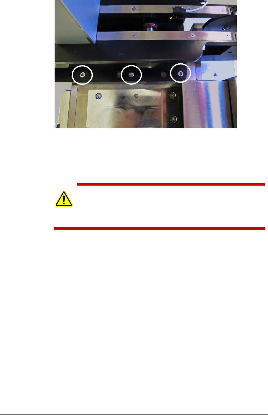
Figure 27: Tape-Output Module mounting screws (circled). Three
more mounting locations are on back side (hidden in this view).
Ref: The Tape-In mount and chute are in the foreground.
SETTING UP THE TAPE OUTPUT MODULE
CAUTION: Possible tape damage from excessive heat! Improper routing
of the device tape may cause enough heat to melt the tape. Ensure the
correct routing path is followed. See the TM-50 Tape Output System
User’s Guide.
To set up the Tape Output System:
1. Edit the winAH400.ini file for Tape Output—
1a. Using Windows Explorer, locate C:\CH700\winAH400.ini
and make a backup copy, for example,
winAH400backup.ini.
1b. Open the original file with Microsoft Notepad.
1c. Locate the line: TapeOutPutInstalled=FALSE and change it
to True: TapeOutputInstalled=TRUE
1d. Save the winAH400.ini file and exit Windows Explorer.
2. The Tape Output Module gets power and air from the PSV5000
System. Connect the compressed air, electrical power, and
communication (Just right below the Tape Output System).
3. Ensure the PSV5000 System air is connected and power is ON.
4. Switch the Tape Output Module ON by pressing the power switch.
■ Setting Up Input and Output Media □ The Tape Output Setup and Operation
PSV5000 Owner’s Manual - 51 -
5. Set the taping job parameters at the controller. For more
information see the TM-50 Tape Output System User’s Guide.
6. Pull the nearest half of the track (table) out to the desired track
width. It stops at detents set to specific tape widths.
7. Mount the carrier tape reel—
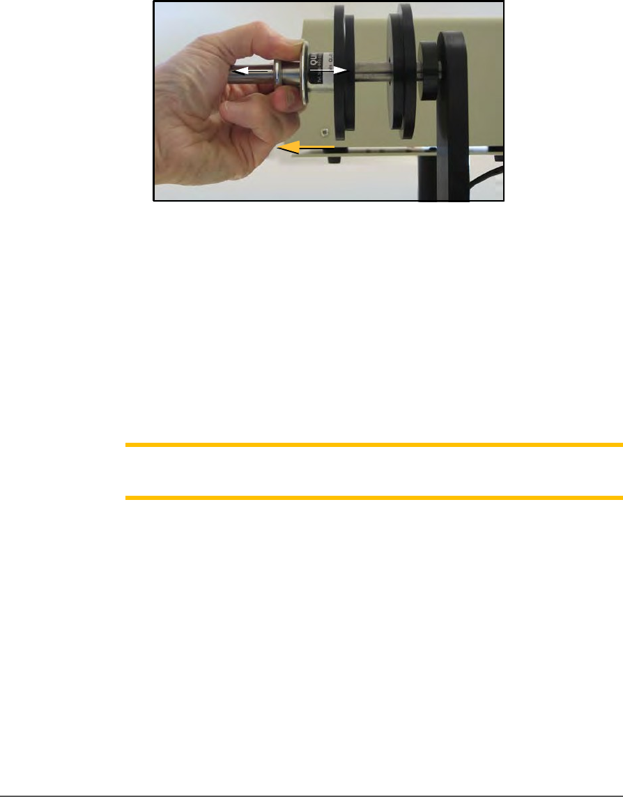
7a. Remove the carrier tape quick lock from the carrier tape
spindle.
Figure 28: Removing the spindle.
7b. Mount the bulk carrier tape reel on the right spindle so the
tape unwinds from the top.
7c. Replace the quick lock.
7d. Trim the end of the carrier tape so it is clean and straight.
8. Route the carrier tape—
8a. Guide the carrier tape into the loading track. It should feed
right to left through the loading track easily.
Note: Lowering the feed reel support arm can reduce drag if the
angle at
which the carrier enters the loading track is too steep.
8b. Bring the end of the carrier tape past the sealer and engage the
sprocket holes on the teeth of the drive sprocket.
9. Mount the cover tape—
9a. Place a reel of cover tape of the correct width to match the
carrier tape on the cover tape spindle. The tape should
unwind to the right from the bottom of the reel.
9b. Set the width of the cover tape guide assembly for your size
tape.
Setup ■ Setting Up Input and Output Media
- 52 - Data I/O ■ 096-0465-001C
9c. Use the Cover Tape Position Adjuster if needed. Turning it
clockwise moves the cover tape position toward the sprocket
side of the tape.
9d. Using blue tabbing tape, attach the cover tape to the carrier
tape. Thread both through the cover tape Guide Sealer
Assembly. Run the machine to advance the carrier and
cover
tapes through the sealer.
PREPARE THE SEAL
Note: Disable the pressure seal by loosening the seal roller pressure
screws until the seal rollers are no longer in contact with the cover tape.
Normally the heat switch is in on position. If not, turn on the heat switch.
To prepare the heat seal
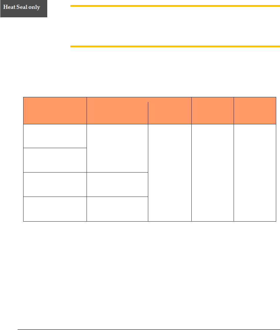
1. Set the temperature controls to the appropriate temperature. See
the table below.
Carrier Tape Type
Cover Tape Type
Temperatur
e
Air
Pressure
Dwell Time
3m Type 3000
Conductive Carrier
3m Type 2675 Static
Dissipative Cover
135-155°C
40-60 PSI
250-400 ms
3m Type 2701/2703
Non-conductive
Advantek
Conductive
Advantek Type AA
Advantek
Non-conductive
Advantek Type S
Figure 29: This table lists suggested temperature and pressure
settings for the Tape Output. The temperature of each shoe can
be increased or decreased according the results of a peel force
test.
2. Adjust the heat shoe air pressure to the appropriate setting. This
setting controls the amount of force applied when the sealer shoes
drop.