PSV5000_OwnersManual.pdf - 第56页
Setup ■ S etting Up In put and Output Media - 52 - Data I/O ■ 096 - 0465 - 00 1C 9c. Use the Co ver T ape P osi ti on Ad ju s ter if ne ede d. T ur ning it cloc kwise mo ves the co v er t ape po si ti on to w a rd the sp…
■ Setting Up Input and Output Media □ The Tape Output Setup and Operation
PSV5000 Owner’s Manual - 51 -
5. Set the taping job parameters at the controller. For more
information see the TM-50 Tape Output System User’s Guide.
6. Pull the nearest half of the track (table) out to the desired track
width. It stops at detents set to specific tape widths.
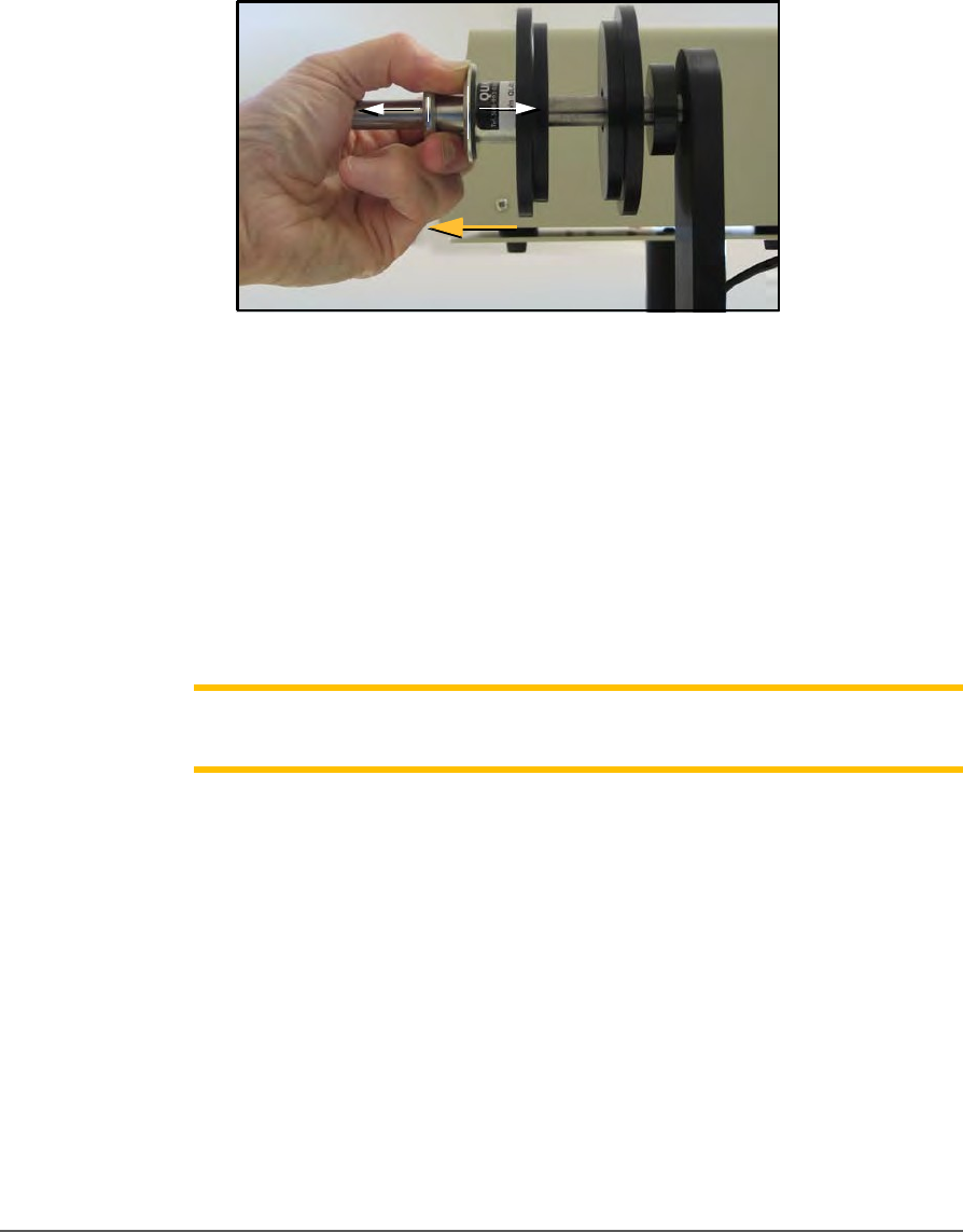
7. Mount the carrier tape reel—
7a. Remove the carrier tape quick lock from the carrier tape
spindle.
Figure 28: Removing the spindle.
7b. Mount the bulk carrier tape reel on the right spindle so the
tape unwinds from the top.
7c. Replace the quick lock.
7d. Trim the end of the carrier tape so it is clean and straight.
8. Route the carrier tape—
8a. Guide the carrier tape into the loading track. It should feed
right to left through the loading track easily.
Note: Lowering the feed reel support arm can reduce drag if the
angle at
which the carrier enters the loading track is too steep.
8b. Bring the end of the carrier tape past the sealer and engage the
sprocket holes on the teeth of the drive sprocket.
9. Mount the cover tape—
9a. Place a reel of cover tape of the correct width to match the
carrier tape on the cover tape spindle. The tape should
unwind to the right from the bottom of the reel.
9b. Set the width of the cover tape guide assembly for your size
tape.
Setup ■ Setting Up Input and Output Media
- 52 - Data I/O ■ 096-0465-001C
9c. Use the Cover Tape Position Adjuster if needed. Turning it
clockwise moves the cover tape position toward the sprocket
side of the tape.
9d. Using blue tabbing tape, attach the cover tape to the carrier
tape. Thread both through the cover tape Guide Sealer
Assembly. Run the machine to advance the carrier and
cover
tapes through the sealer.
PREPARE THE SEAL
Note: Disable the pressure seal by loosening the seal roller pressure
screws until the seal rollers are no longer in contact with the cover tape.
Normally the heat switch is in on position. If not, turn on the heat switch.
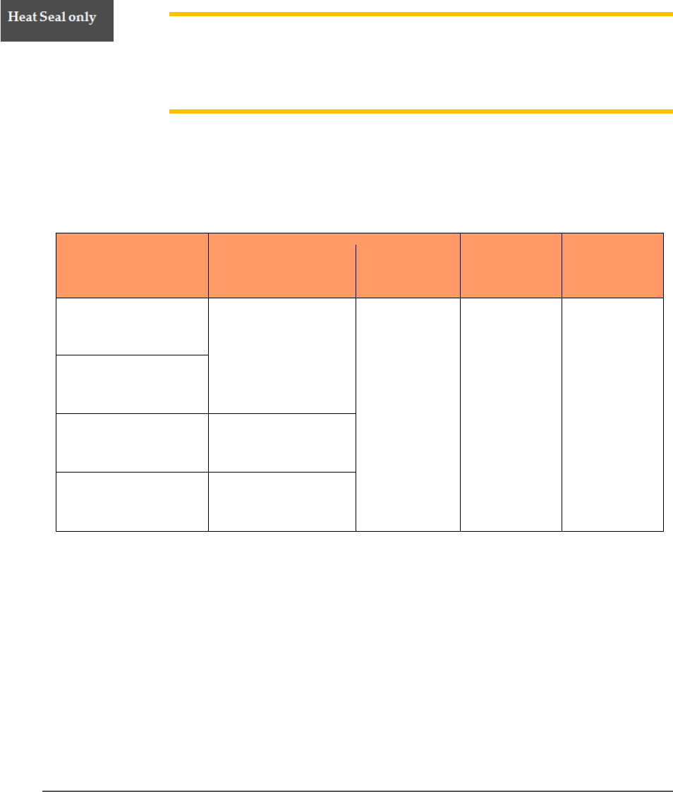
To prepare the heat seal
1. Set the temperature controls to the appropriate temperature. See
the table below.
Carrier Tape Type
Cover Tape Type
Temperatur
e
Air
Pressure
Dwell Time
3m Type 3000
Conductive Carrier
3m Type 2675 Static
Dissipative Cover
135-155°C
40-60 PSI
250-400 ms
3m Type 2701/2703
Non-conductive
Advantek
Conductive
Advantek Type AA
Advantek
Non-conductive
Advantek Type S
Figure 29: This table lists suggested temperature and pressure
settings for the Tape Output. The temperature of each shoe can
be increased or decreased according the results of a peel force
test.
2. Adjust the heat shoe air pressure to the appropriate setting. This
setting controls the amount of force applied when the sealer shoes
drop.
■ Setting Up Input and Output Media □ The Tape Output Setup and Operation
PSV5000 Owner’s Manual - 53 -
Note: The recommended starting point for heat shoe air pressure is 50 PSI.
Turning the heat shoe adjuster clockwise increases the pressure.
3. After the heat sealer reaches operating temperature, set the
controller parameters, if not already set.
4. Press Start in the LCD.
5. Advance the tape using the Manual Trig button in the LCD.
6. Check the sealed tape for the desired sealed position.
7. If necessary, adjust the inner seal position by turning the inner
seal adjuster (thumb wheel) clockwise (to move the seal away from
the operator) or counterclockwise. Tighten the position lock to
secure it.
8. If necessary, adjust the outer seal position by turning the outer
seal adjuster (thumb wheel) clockwise to move the seal toward the
operator or counterclockwise (to move the seal away from the
operator). Lock the adjuster into place using the position lock
knob.
For Pressure Seal (PSA)
1. To prepare the pressure seal. Set the temperature to Room
Temperature, 25℃ .
2. Advance the tape using Manual Trig button in the LCD.
3. Adjust the inner and outer seal roller position. Align the roller
position over the strip of adhesive on either side of the PSA cover
tape. Both thumb screws have locking devices.
4. Adjust the pressure at both sealer wheels to free spinning and then
1/8 revolution tighter. Use a 2 mm hex key.
5. Advance the tape using the Manual Trig button in the LCD.
Re-adjust the seal roller pressure until the PSA adhesive is firmly
adhered to the carrier tape.
Note: Excessive roller pressure may cause carrier tape advance problems
or elongation of sprocket holes in the carrier tape.
CHECKS TO PERFORM PRIOR TO RUNNING
6. Mount an empty take-up reel on the spindle.
7. Perform a Peel Force Test Perform as many peel force tests as
needed while adjusting the sealer controls to obtain the required
seal strength.