PSV5000_OwnersManual.pdf - 第59页
■ Setting U p the Lase r Mar king M odule □ Preparation: PSV5000 O wner ’s M anual - 55 - Setting Up the Lase r Marking Module Prepa rati on: 1. Ma ke sure a USB dongle for the laser has been updated. 2. Upgrade CH700 to…

Setup ■ Setting Up Input and Output Media
- 54 - Data I/O ■ 096-0465-001C
Remember: when the
reel is being taped on
the TM-50, the trailer
will be the first length
of empty carrier tape
run before the first
device is taped, and
the leader will be the
length of empty
carrier tape run after
the last device is
8. Create the Trailer and Leader Before beginning a production reel,
determine how long the trailer and the leader should be. Run out
enough sealed empty pockets to make the trailer that is required
for the current job.
9. Check Carrier Tape Alignment To ensure an accurate count, select
a spot on the loading track as a reference point for the first and last
devices counted.
10. Set the Counter Set the counter STOP value in the LCD to a big
number as 9,999.
Note: Use the counter on the Tape output system if desired. However, we
recommend setting this counter to zero and using the pass quantity on the
PSV5000 System to monitor quantity.
Note: When starting a job that uses Tape Output, pull the red “E-Stop/On”
button on the taping machine to start it.
PLACING DEVICES
Devices are placed by the PNP head when your job is run.
ENDING A TAPED RUN
See the PSV5000 Operators Manual or the TM-50 Tape Output System
User’s Guide.
REPLACING A FULL TAKE UP REEL
See the PSV5000 Operators Manual or the TM-50 Tape Output System
User’s Guide.
REMOVING A TAPE OUTPUT MODULE
Removal of the Tape Output Module is in the reverse order of installation.
See the instructions above.

■ Setting Up the Laser Marking Module □ Preparation:
PSV5000 Owner’s Manual - 55 -
Setting Up the Laser Marking
Module
Preparation:
1. Make sure a USB dongle for the laser has been updated.
2. Upgrade CH700 to V2.3 by installer.
3. Copy CH700.exe (v2.3.2) from
\\sol\ProjDocs\PSV5000 -
1071\Software\CH700 v2.3.2 to C:\CH700 to replace exe of v2.3.
4. Update below values in the package file
5. #134 1500 MSEC, LASER SHUTTLE MOVING TIME
6. #137 0 NUM, INCREASE OR DECREASE LASER
POWER OF CUP2 BASED ON CUP1
7. #138 0 NUM, DISTANCE BETWEEN CUP1 AND
CUP2 IN X DIRECTION
8. #139 -42000 NUM, DISTANCE BETWEEN CUP1
AND CUP2 IN Y DIRECTION
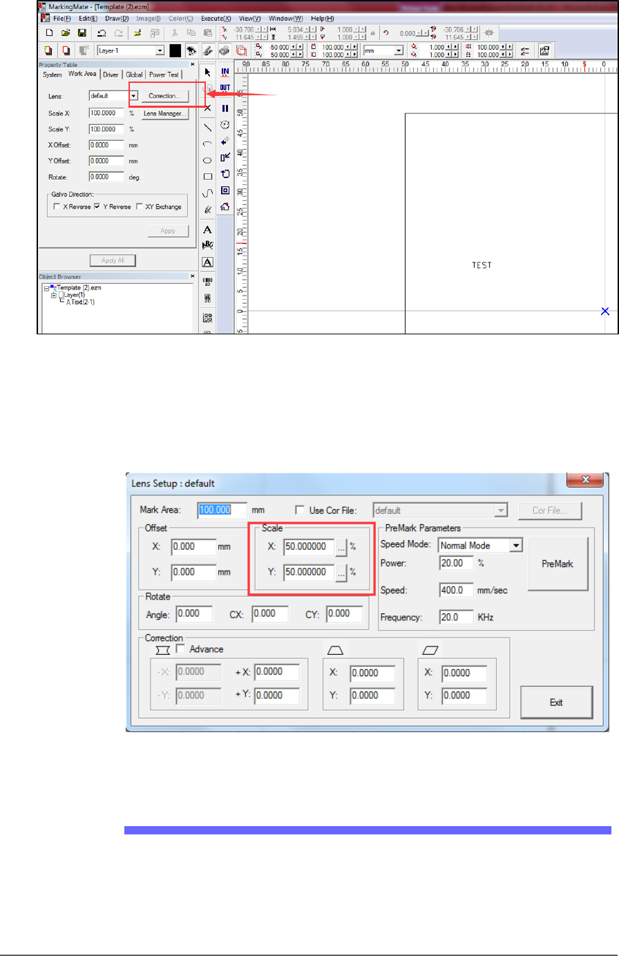
5. Start ‘MarkingMate.exe.’
6. Click a blank space on work area, and then at the Property Table,
click Work Area tab, and click Lens Correction to open the Lens
Setup dialog.
Setup ■ Setting Up the Laser Marking Module
- 56 - Data I/O ■ 096-0465-001C
Figure 30: The Lens Correction button in the MarkingMate software.
7. Confirm scale settings are the same as shown in Figure 32: below.
They are system values: confirm or calibrate initially and each time
there is a hardware change.
Figure 31: The Scale factors in the Lens Setup dialog.
Laser Software Instruction
1. Copy Template.ezm and rename it for your job, or start the
MarkingMate.exe to create a new blank file and then add a text
string into the work area for marking.