PSV5000_OwnersManual.pdf - 第62页
Setup ■ Setting U p the Laser Mar king Modul e - 58 - Data I/O ■ 096 - 0465 - 00 1C b) Set L aserR emoteConn ection=L OCAL to choose a laser control method . No te : Load M arking Data can s how ‘M arkin gMate’ Sof t wa …
■ Setting Up the Laser Marking Module □ CH700 Configuration
PSV5000 Owner’s Manual - 57 -
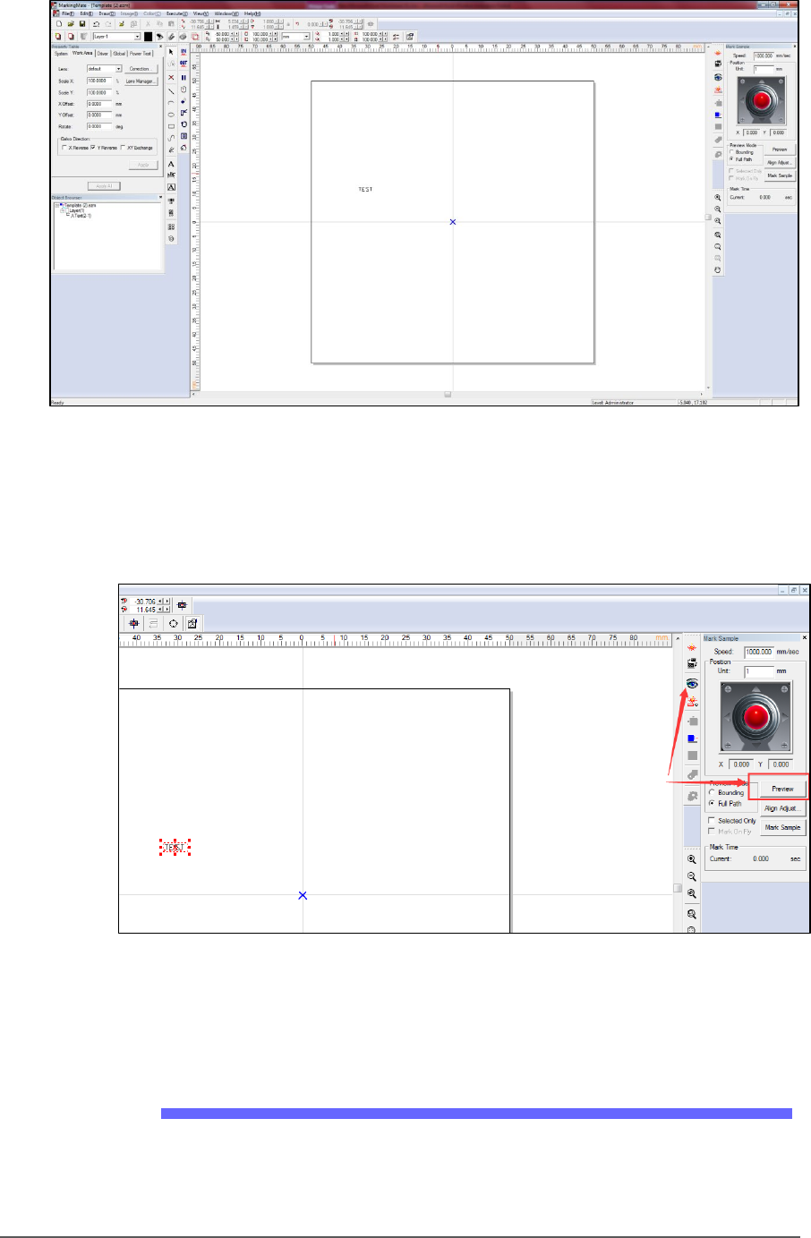
Figure 32: Adding text to mark the devices.
2. Enter preview mode (see image below) to confirm the real world
marking position is set to Cup1 of shuttle. Move the red light to
cup1 position using the arrow key if they do not match.
Figure 33: The Preview button.
3. Save the file and exit the software.
CH700 Configuration
1. Make a backup of the winAH400.ini file.
2. In the winAH400.ini file make the following changes:
a) Set MarkerSystem=UPRHAND to enable the laser.
Setup ■ Setting Up the Laser Marking Module
- 58 - Data I/O ■ 096-0465-001C
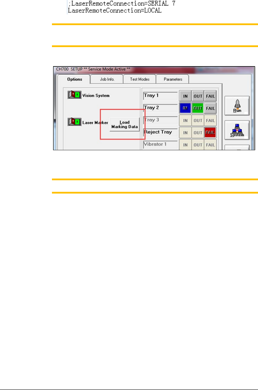
b) Set LaserRemoteConnection=LOCAL to choose a laser control
method.
Note:
Load Marking Data
can show ‘MarkingMate’ Software for marking
content edits.
Figure 34: The Load Marking Data button in the CH700 Setup window
opens the MarkingMate Software.
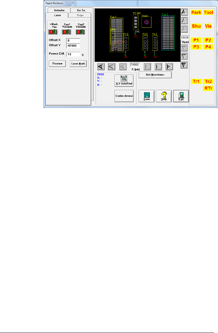
Note: Cup1 position must be set correctly by
MarkingMate
.
3. Click System > Gantry > Laser tab.
a. Switch on Cup1 Vac then click Preview to confirm red light
aims at cup1. If not please run Markingmate to move the red
light to match cup1.
b. Switch on Cup2 Vac and click Preview and set red light for
cup2. Change Offset X / Offset Y to set distance between cup1
and cup2 in X/Y directions.
c. The Power Diff. field is the laser energy diference between cup1
and cup2; for example, if power of cup1 is set to 20%, here set
to 10% means power is 30% for cup2.
d. After setting the proper positions, click Laser Mark to check
real marking results.