PSV5000_OwnersManual.pdf - 第63页
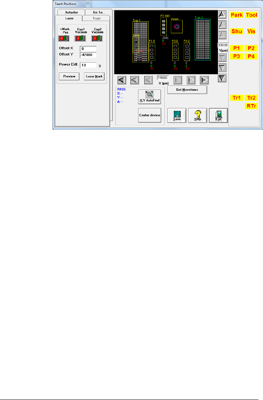
■ Setting U p the Lase r Mar king M odule □ CH700 Configur ation PSV5000 O wner ’s M anual - 59 - Figur e 35: The Laser ta b in the Gantr y wind ow . See instr uctions in st ep 3 abo ve for descriptions of controls on th…
Setup ■ Setting Up the Laser Marking Module
- 58 - Data I/O ■ 096-0465-001C
b) Set LaserRemoteConnection=LOCAL to choose a laser control
method.
Note:
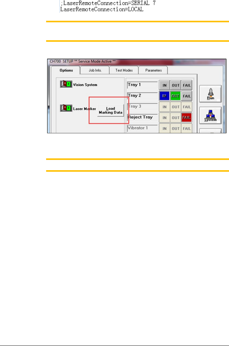
Load Marking Data
can show ‘MarkingMate’ Software for marking
content edits.
Figure 34: The Load Marking Data button in the CH700 Setup window
opens the MarkingMate Software.
Note: Cup1 position must be set correctly by
MarkingMate
.
3. Click System > Gantry > Laser tab.
a. Switch on Cup1 Vac then click Preview to confirm red light
aims at cup1. If not please run Markingmate to move the red
light to match cup1.
b. Switch on Cup2 Vac and click Preview and set red light for
cup2. Change Offset X / Offset Y to set distance between cup1
and cup2 in X/Y directions.
c. The Power Diff. field is the laser energy diference between cup1
and cup2; for example, if power of cup1 is set to 20%, here set
to 10% means power is 30% for cup2.
d. After setting the proper positions, click Laser Mark to check
real marking results.

PSV5000 Owner’s Manual - 60 -
Chapter Three 3 —
Administrative Functions
The two primary levels of operation of PSV5000 are •
Operator functions, and • Administrator functions.
Only Administrator functions are covered in this manual.
Operator functions are covered in the separate PSV5000 Operators
Manual, although Administrators should be familiar with all operator
functions.
Administrators generally follow the sequence on the next page to create
a job: