PSV5000_OwnersManual.pdf - 第86页
Ad ministrati ve F unctions ■ Marking Option - 82 - Data I/O ■ 096 - 0465 - 00 1C a. Loosen the scr ew on the lower left of a rectan gular safet y shield s hown in Figu re 47: (4 mm he x key). b. Unscrew t he top screw (…
Marking Option ≡ Installing the Laser Shuttle Module
PSV5000 Owner’s Manual - 81 -
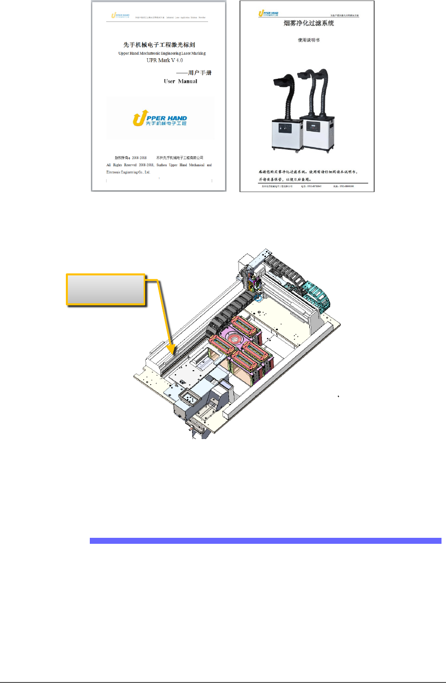
Figure 44: Manuals for the laser device marker and Fume Extractor.
Figure 45: Laser marking uses a laser shuttle except when using
Tape-Output. The shuttle is installed at the factory to transport
devices to the laser beam.
Installing the Laser Shuttle Module
TOOLS REQUIRED
Metric Hex Key set
To install the Laser Shuttle Module:
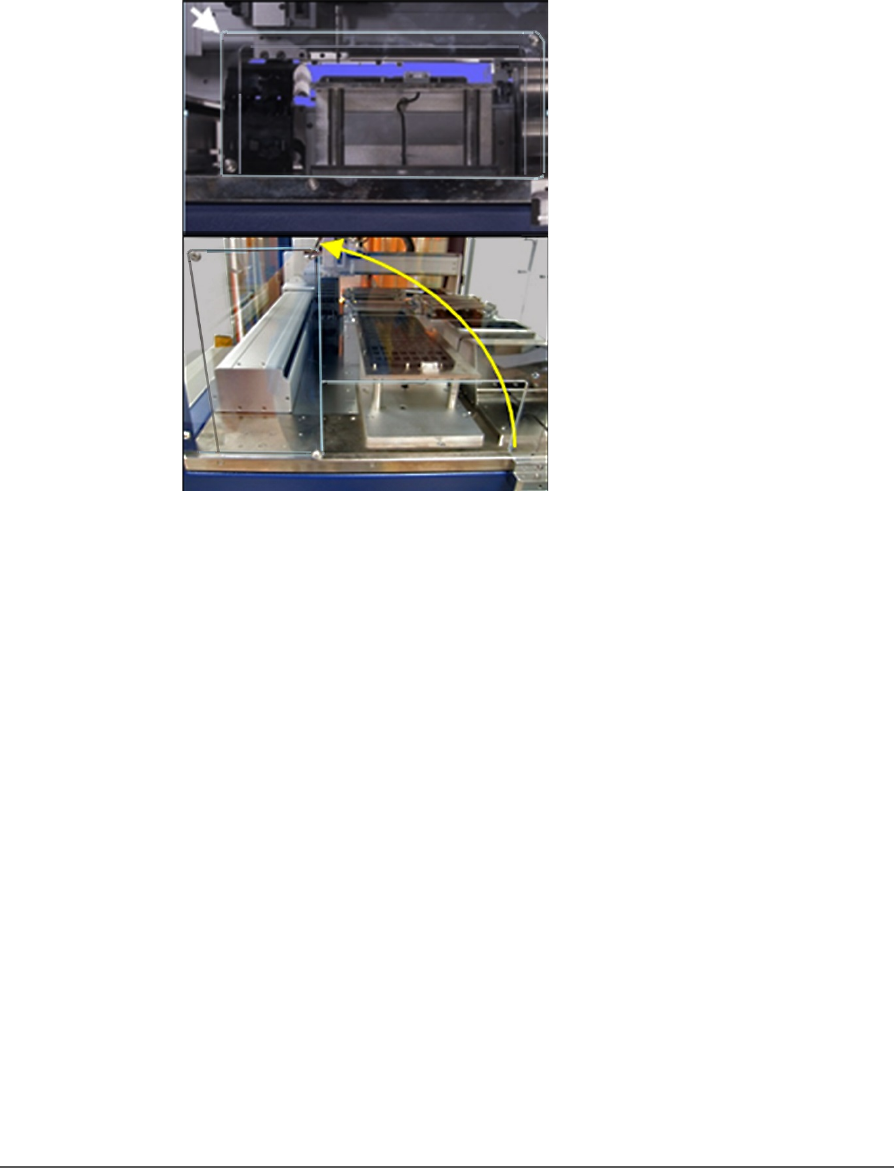
1. On the left side of the machine prepare the small clear safety covers
for receiving the Laser Shuttle Module.
Laser Shuttle
Administrative Functions ■ Marking Option
- 82 - Data I/O ■ 096-0465-001C
a. Loosen the screw on the lower left of a rectangular safety
shield shown in Figure 47: (4 mm hex key).
b. Unscrew the top screw (4 mm hex key).
c. Rotate the rectangular shield counterclockwise 90°to the
‘storage’ position and screw it to the fixed safety shield with
the screw you just removed. Refer to the figure below.
Figure 46: To install the Laser Shuttle Module, rotate the shield
counterclockwise 90°.
2. Unscrew the five screws that secure large fixed safety shield
(4 mm
hex key).
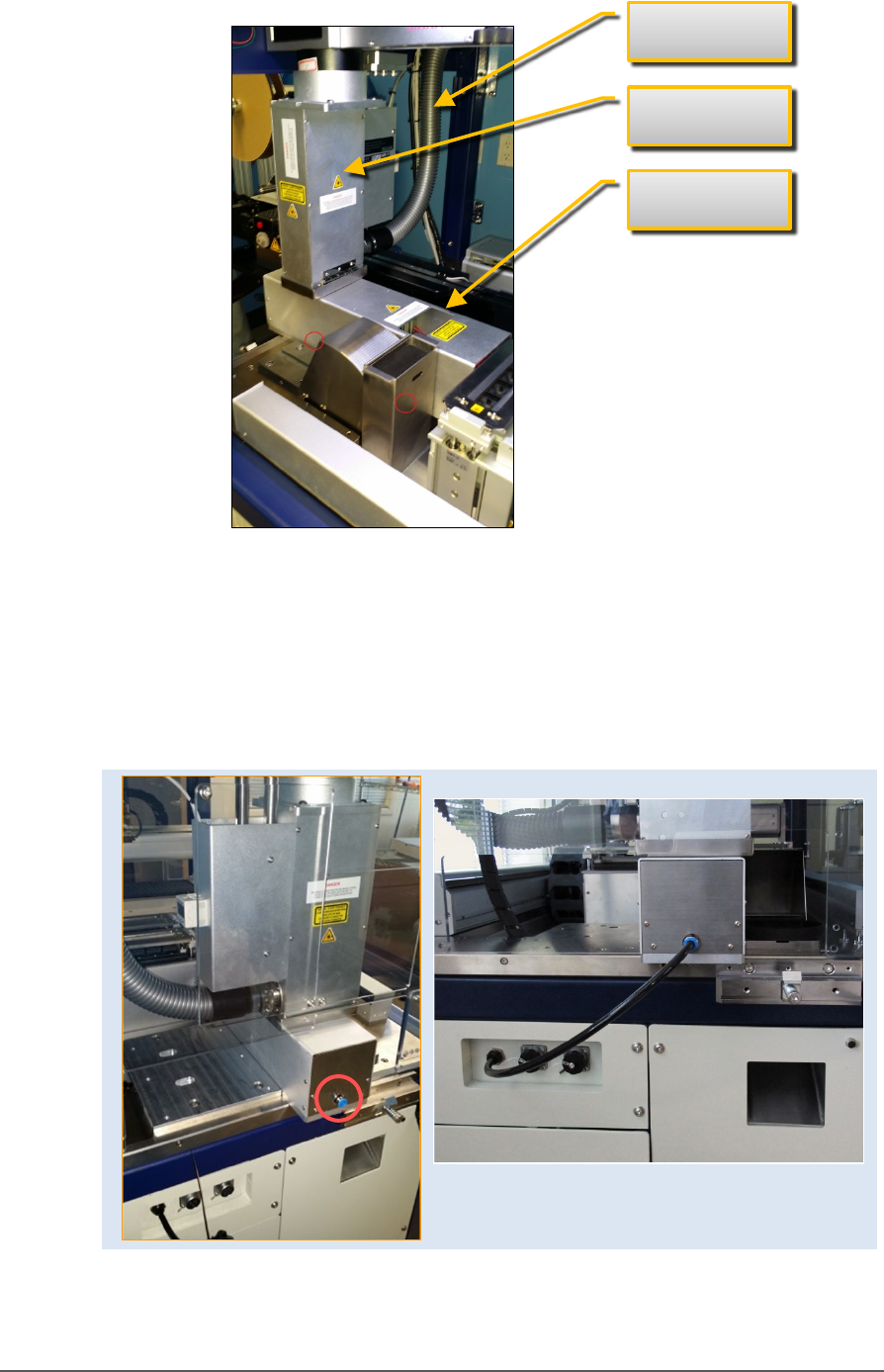
3. Install the Laser Shuttle Module onto the plate in the PSV5000
workspace and screw it down with two screws (5 mm hex key) from
the underside of the plate . See the figure below.
Marking Option ≡ Installing the Laser Shuttle Module
PSV5000 Owner’s Manual - 83 -
Figure 47: Laser Shuttle fasteners are on the underside at
approximately the two circled locations (near side only shown).
4. Connect the air tube to the machine, two connectors are shown
below.
5. Connect the communications cable to the left side of the machine.
Figure 48: Left: the Laser Shuttle air connection (circled). Right:
connected.
Laser safety
shield
Laser Shuttle
Laser Exhaust