PSV5000_OwnersManual.pdf - 第87页
Marking Option ≡ Install ing th e Laser Shutt le Mod ule PSV5000 O wner ’s M anual - 83 - Figure 47: Lase r Shuttle fa steners are on the u nderside a t approx imately the two circled lo cations (nea r side only shown …
Administrative Functions ■ Marking Option
- 82 - Data I/O ■ 096-0465-001C
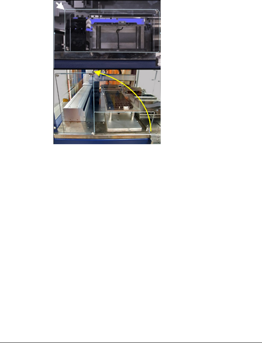
a. Loosen the screw on the lower left of a rectangular safety
shield shown in Figure 47: (4 mm hex key).
b. Unscrew the top screw (4 mm hex key).
c. Rotate the rectangular shield counterclockwise 90°to the
‘storage’ position and screw it to the fixed safety shield with
the screw you just removed. Refer to the figure below.
Figure 46: To install the Laser Shuttle Module, rotate the shield
counterclockwise 90°.
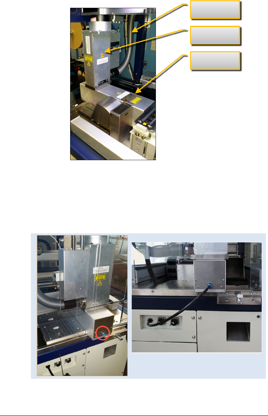
2. Unscrew the five screws that secure large fixed safety shield
(4 mm
hex key).
3. Install the Laser Shuttle Module onto the plate in the PSV5000
workspace and screw it down with two screws (5 mm hex key) from
the underside of the plate . See the figure below.
Marking Option ≡ Installing the Laser Shuttle Module
PSV5000 Owner’s Manual - 83 -
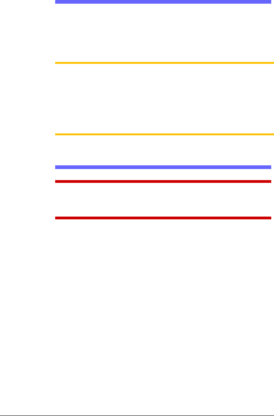
Figure 47: Laser Shuttle fasteners are on the underside at
approximately the two circled locations (near side only shown).
4. Connect the air tube to the machine, two connectors are shown
below.
5. Connect the communications cable to the left side of the machine.
Figure 48: Left: the Laser Shuttle air connection (circled). Right:
connected.
Laser safety
shield
Laser Shuttle
Laser Exhaust
Administrative Functions ■ Marking Option
- 84 - Data I/O ■ 096-0465-001C
Creating a Laser Marking File
Laser graphics used to mark devices are generated using the
MarkingMate software included with the Laser Option. It resides in the
Laser Computer. Any style of marking (whether text-based,
graphic-based, or both) can be generated and used for marking devices.
The only limitation is the size of the device to be marked.
NOTE: For instructions creating an image file for the Laser System, see:
• the Laser_Configuration_And_Operation.pdf (customer letter
983-5075-001A.pdf) on the Handler PC if your programmer was ordered
with the laser option, or see the software operation disc for the
MarkingMate software.
• the CH700 on-screen Help topic Setting up and Teaching > Create a
Laser Marking File.
Verifying Proper Laser Operation
WARNING: Possible health hazard from toxic fumes! Laser marking
generates vapors, fumes, and particles that can be noxious, toxic. Follow
maintenance procedures. Use proper ventilation.
REQUIREMENTS
• An image file is in the MarkingMate SW application.
To verify that the laser is marking as expected:
1. Put one device on the expected marking position.
2. At the Laser window, click Laser Marker. This device will be marked.