SP08.pdf - 第15页
8. Remove the “Air Out” flexible hose from the motor enclosure, this allows the top cover of the motor enclosure to be removed exposing the motors. 9. Remove the spring clip from the brushes, remove the black cover from …
INSPECTION AND REPLACEMENTS
Electric Motor Carbon Brushes
Inspection Tools Required: 1x Pozidrive screw driver medium
1x Pozidrive screw driver small
1x Flat-bladed Screw driver small
1. Isolate the unit from the machine supplies and mains power.
2. Identify the 3 pan head screws at the top of the rear panel and remove them.
3. Remove the top cover by lifting it from the rear and sliding to the front of the
unit.
4. Disconnect the motor supply IEC connection from the electrical enclosure,
pivot the electrical enclosure to give full access to the top of the unit.
5. Remove the “Air Out” flexible hose from the exhaust positioned in the rear
right-hand corner, this requires a firm twist and pull to remove the hose.
6. The motor enclosure may now be lifted clear of the vacuum unit and placed
on a work surface.
7. Removal of the motor enclosure exposes the third stage filter ozone filter and
pre-filter should these need checking or replacement.
12 DEK Printing Machines Ltd Issue 3. Nov 00
DEK VACUUM AND FILTRATION UNIT SP08
INSPECTION AND REPLACEMENTS
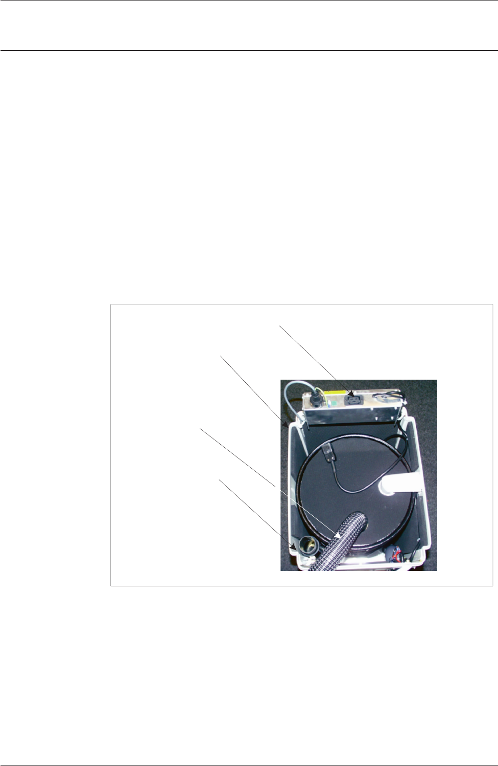
IEC Cover
Electrical Enclosure
Exhaust Silencer
Air Out Hose
Figure 4 Vacuum Motor Components
8. Remove the “Air Out” flexible hose from the motor enclosure, this allows
the top cover of the motor enclosure to be removed exposing the motors.
9. Remove the spring clip from the brushes, remove the black cover from each
motor.
10. Remove the bracket from each brush, disconnect the electrical connection
and remove each brush housing.
Issue 3. Nov 00 DEK Printing Machines Ltd 13
DEK VACUUM AND FILTRATION UNIT SP08
INSPECTION AND REPLACEMENTS
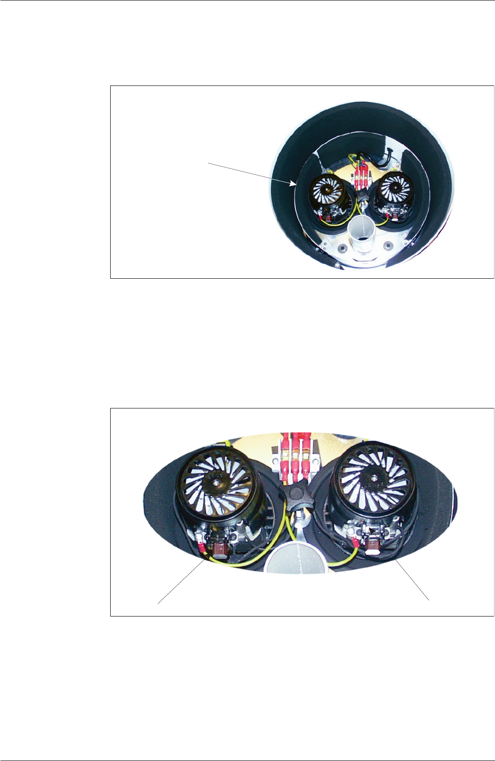
Plastic Motor Cover
Figure 5 Motor Cover
Spring Clips
Brushes
Figure 6 Spring Clips and Brushes
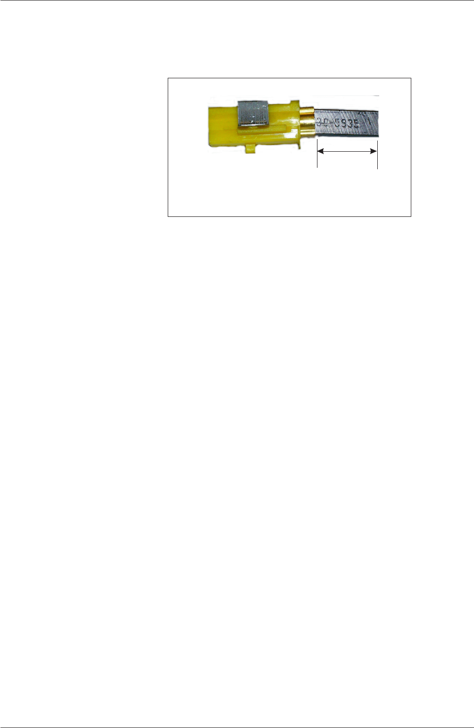
11. Check the length of the carbon head remaining, if less than 6mm the brushes
require replacement.
12. With the brushes out, inspect the motor commutator for signs of wear,
carbon deposit build up or short circuits. Clean as appropriate.
13. Refit the motor enclosure to the vacuum unit in the reverse order, ensure the
“Air Out” flexible hose is secure on the exhaust (positioned on the rear right
hand corner).
14. Reconnect the vacuum unit on the machine and copnnect mains power.
15.
Enter Diagnostics and select Screen Cleaner, to test operation of the unit.
NOTES:
1. When changing carbon brushes, BOTH brushes must be changed at the
same time, ie a pair of replacement brushes contain one Auto Stop and one
Standard brush.
2. It is also advisable to bed the new carbon brushes in by running the
motors at 50% speed for 10 minutes.
14 DEK Printing Machines Ltd Issue 3. Nov 00
DEK VACUUM AND FILTRATION UNIT SP08
INSPECTION AND REPLACEMENTS
Minimum Brush Length
6mm
Figure 7 Brush Length