SP08.pdf - 第6页
DESCRIPTION General The unit has been designed for ease of service and minimal tools required. The unit incorporates an integral 2-stage silencer assembly that does not require maintenance. The noise level of the free-st…

INTRODUCTION
PHILOSOPHY / PURPOSE
To provide high flow vacuum for the purpose of removing printing matter
residue, ie solder paste, from the apertures of stencils used in DEK printing
machines during an automatic underscreen clean cycle.
To eliminate fumes, odours, possible explosive gases and hazardous particles
that may be created by the solders and solvents used during screen cleaning by
DEK printing machines, from passing into the atmosphere.
To be environmentally friendly.
To increase the speed and efficiency of screen cleaning.
To operate at low noise values.
To give clear indications of operating status and elapsed use.
To be easily maintained.
Issue 3. Nov 00 DEK Printing Machines Ltd 3
DEK VACUUM AND FILTRATION UNIT SP08
INTRODUCTION

DESCRIPTION
General The unit has been designed for ease of service and minimal tools required.
The unit incorporates an integral 2-stage silencer assembly that does not require
maintenance. The noise level of the free-standing unit is 57dB.
NOTE:
The air is expelled at the rear of the unit at ground level. This area should be kept
clear and allowances should be made if situated near cooling or environmental
control auxiliary units or devices.
Elements The unit comprises:
•
Air-in Chamber
•
Integral Silencer
•
Power Control Box
• 3 part Modular Sections
• Front Control Panel
• Rear Connection Panel
Air-In Chamber The polluted air is piped to this chamber, which is fixed to the base of the
cabinet. This chamber also supports the pre-filter.
Integral Silencer The Integral Silencer is situated in the base at the rear of the cabinet.
Power Control Box The Power Control Box is situated at the front top of the cabinet.
Module 1 By-pass cooling assembly.
Module 2 Vacuum pump assembly.
Module 3 Ozone Filter.
Front Control Panel This panel provides all the indicators and controls for the operator interface.
Rear Connection
Panel
This panel houses the power and external control connections and respective
protective fuses.
All the above are housed in an attractively designed ABS cabinet.
4 DEK Printing Machines Ltd Issue 3. Nov 00
DEK VACUUM AND FILTRATION UNIT SP08
DESCRIPTION
Issue 3. Nov 00 DEK Printing Machines Ltd 5
DEK VACUUM AND FILTRATION UNIT SP08
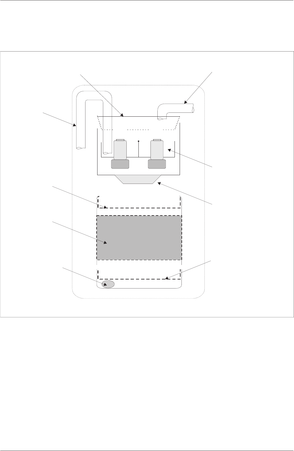
DESCRIPTION
3rd Stage Filter
By-pass Cooling Assembly
HP Air Out
LP Air In
HEPA Filter
Pre-filter
Vacuum Pump Assembly
Ozone Filter
Cyclonic Entry for
High Pressure Air In
Figure 1 Layout of Internal Components