Maintenance Manual.pdf - 第135页
AV131 MAINTENANCE MANUAL 7.2 Per iodic Inspecti on Items D79MEC- Z0-020- A0 7.2- 2 7.2. 2 Weekl y Check Item s The f ollowi ng table summariz es the peri od i c inspecti on it e m s that are t o be per f orm ed w eekl y.…
AV131
MAINTENANCE MANUAL
7.2 Periodic Inspection Items
D79MEC-Z0-020-A0
7.2-1
7.2. Periodic Inspection Items
D79MEC-Z0-020-A0
7.2.1 Daily Check Items
The following tables summarize the periodic inspection items that are to be performed daily.
For the details of inspection positions and lubrication method, refer to the subsequent sections.
Numbers in the Unit column show the relevant sections to be referred to.
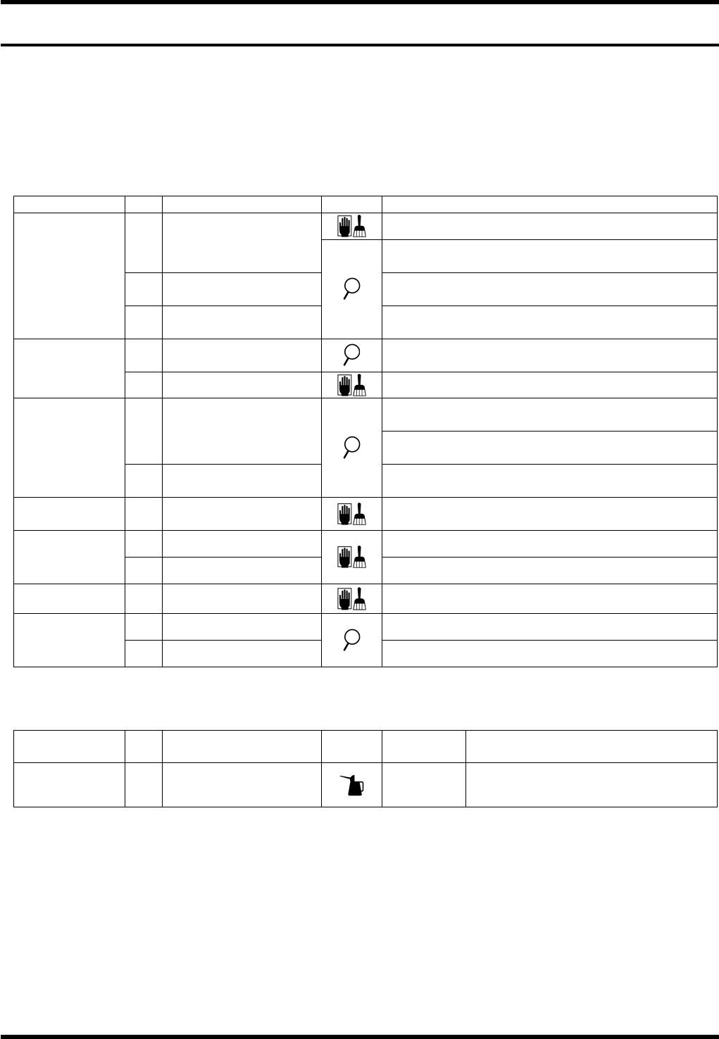
Inspection (Daily)
Unit No. Item Task Description
Remove foreign matter or dust.
a. Cutter blade
Make sure that the cutter blade is not worn or
damaged.
b. Insertion guide
Make sure that the insertion guide is not worn or
damaged.
7.6.2
Insertion Unit
c. Bending die
Make sure that the tip of the bending die is not
worn or damaged.
a. Groove cam
Make sure that the groove cam slides smoothly
and there is no abnormal noise at the joint.
7.8.2
Transfer Chuck
b. Piston & chuck
Remove dirt or dust.
Make sure that the tip of the cutter & clincher blade
is not worn or damaged.
a. Cutter & clincher
Make sure that the cutter & clincher moves
smoothly without abnormal noises.
7.9.1
Upper Anvil
b. Clinch base
Make sure that the tip of the clinch base blade is
not worn or damaged.
7.10.1
Tape Cutter
a.
Component detection
sensor
Remove oil or dust.
a. Dust collecting box Dispose of cut waste.
7.10.2
Dust Collecting
Box
b. Filter
Remove dirt or dust.
7.11.1
Vacuum Pump
c. Waste receptacle
Dispose of cut waste.
b. Main pressure Make sure that air pressure is at 0.5 MPa.
7.11.2
Pneumatic
Circuit
c. Pneumatic circuit
Make sure that there is no air leakage.
Oiling (Daily)
Unit No. Item Work
Oiling
volume
Description
7.11.2
Pneumatic
Circuit
1. Pneumatic circuit
10 drops
Refer to instructions in 7.11.2 for
details.
AV131
MAINTENANCE MANUAL
7.2 Periodic Inspection Items
D79MEC-Z0-020-A0
7.2-2
7.2.2 Weekly Check Items
The following table summarizes the periodic inspection items that are to be performed weekly.
For the details of inspection positions and lubrication method, refer to the subsequent sections.
Numbers in the Unit column show the relevant sections to be referred to.
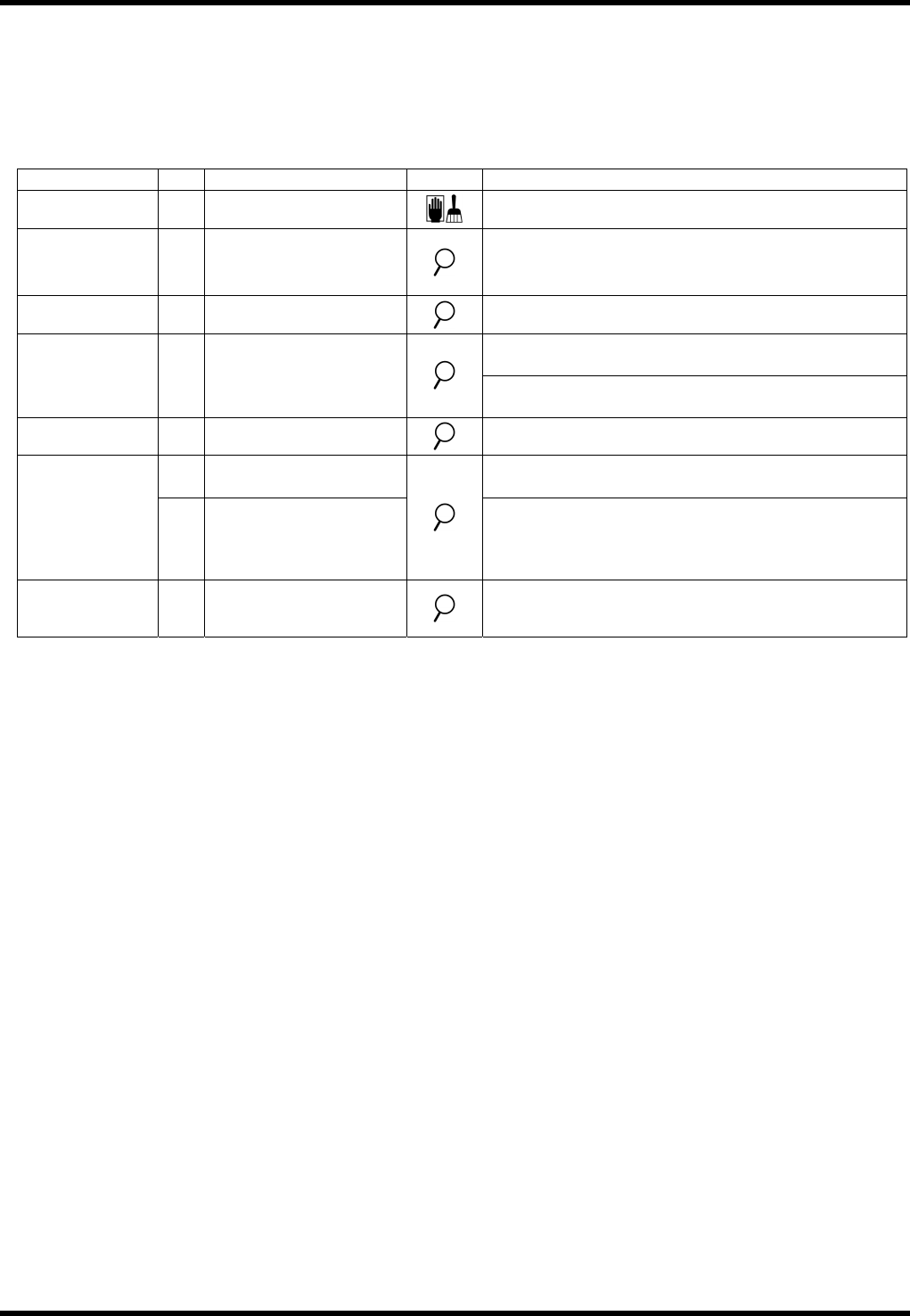
Inspection (Weekly)
Unit No. Item Task Description
7.4.1
Transfer Rail
a. Photo sensor
Remove oil or dust.
7.5.1
Positioner
a. Reference pin
Make sure that the reference pin is not worn or
damaged.
7.6.6
Main Unit
a. Manual rotation wheel
Make sure that the gear rotates smoothly.
Make sure that the transfer pin claw is not
loosened.
7.7.2
PCB Transfer
Unit
a. Transfer pin
Make sure that the transfer pin claw is not
damaged or deformed.
7.10.1
Tape Cutter
b. Cutter condition check
Check it by cutting a piece of paper.
a. Element
Make sure that the vacuum pump filter element is
not clogged or damaged.
7.11.1
Vacuum Pump
b. Hose
Make sure that the hose is not damaged.
Make sure there is no abnormal noises.
Checking is easy with the transparent hose
within the anvil.
7.11.2
Pneumatic
Circuit
a. Oil level
Make sure that the oil level is between the
maximum and minimum limits.
AV131
MAINTENANCE MANUAL
7.2 Periodic Inspection Items
D79MEC-Z0-020-A0
7.2-3
7.2.3 Biweekly Check Items
The following tables summarize the periodic inspection items that are to be performed every other week.
For the details of inspection positions and lubrication method, refer to the subsequent sections.
Numbers in the Unit column show the relevant sections to be referred to.
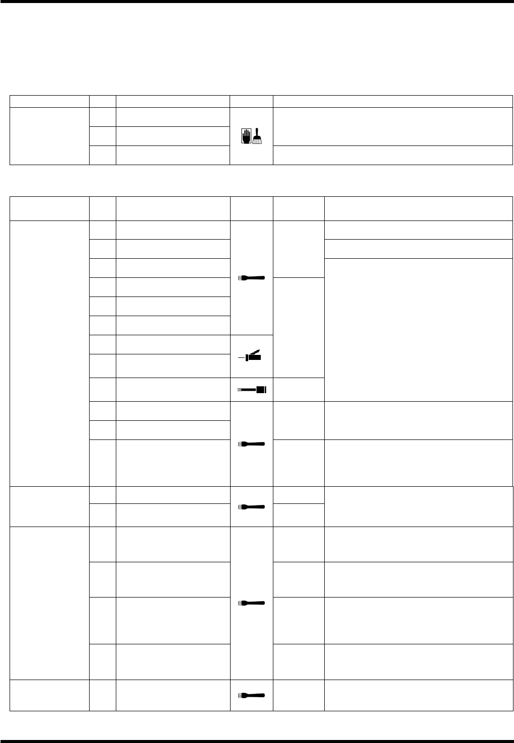
Inspection (Every other week)
Unit No. Item Task Description
c. Ball screw
d. LM guide
Remove dirt or dust.
7.9.1
Upper Anvil
e. Waste intake
Remove any wastes.
Oiling (Every other week)
Unit No. Item Task
Oiling
volume
Description
1. Pusher Position: Up/down sliding surfaces
2. Insertion guide
3. Slide cam
0.05 cm
3
4. Guide
5. Guide base
6. Roller and slide cam
7. Pin and block lever
8.
Pin, lever and guide
base
0.02 cm
3
9.
Pin, bracket and
bending die
0.01 cm
3
Position: Sliding surface
10. Pusher
11. Insertion guide
0.02 cm
3
Position: Sliding surface in the direction
of pitch
7.6.2
Insertion Unit
12.
Fitting surfaces
between the insertion
guide and the slide
cam
0.01 cm
3
Position: Fitting surface
1. Ball screw 0.5 cm
3
7.6.3
Insertion Unit
Drive
2. LM guide (2 areas)
0.1 cm
3
each
Apply grease after removing all foreign
matters.
2.
Sliding surfaces
between the cam
follower and the rod
0.5 cm
3
4.
Sliding surfaces
between the shaft and
the block.
0.1 cm
3
5.
Sliding surfaces
between the rod and
the bush (Insertion
Head) (2 areas)
0.1 cm
3
each
7.6.4
JW Head Unit
(Drive)
(Option)
6.
Sliding surfaces
between the shaft and
the cam follower
0.1 cm
3
7.6.5
JW Head Unit
(Option)
1.
Jumper wire setting
knob
0.5 cm
3
each
Position: Sliding surface