Maintenance Manual.pdf - 第137页
AV131 MAINTENANCE MANUAL 7.2 Per iodic Inspecti on Items D79MEC- Z0-020- A0 7.2- 4 Uni t No. Item T ask Oilin g vol ume Descrip tion 1. LM gui de for 90 ° rot ati on chuck (4 areas) 2. LM guide f or i nserti on unit tr a…
AV131
MAINTENANCE MANUAL
7.2 Periodic Inspection Items
D79MEC-Z0-020-A0
7.2-3
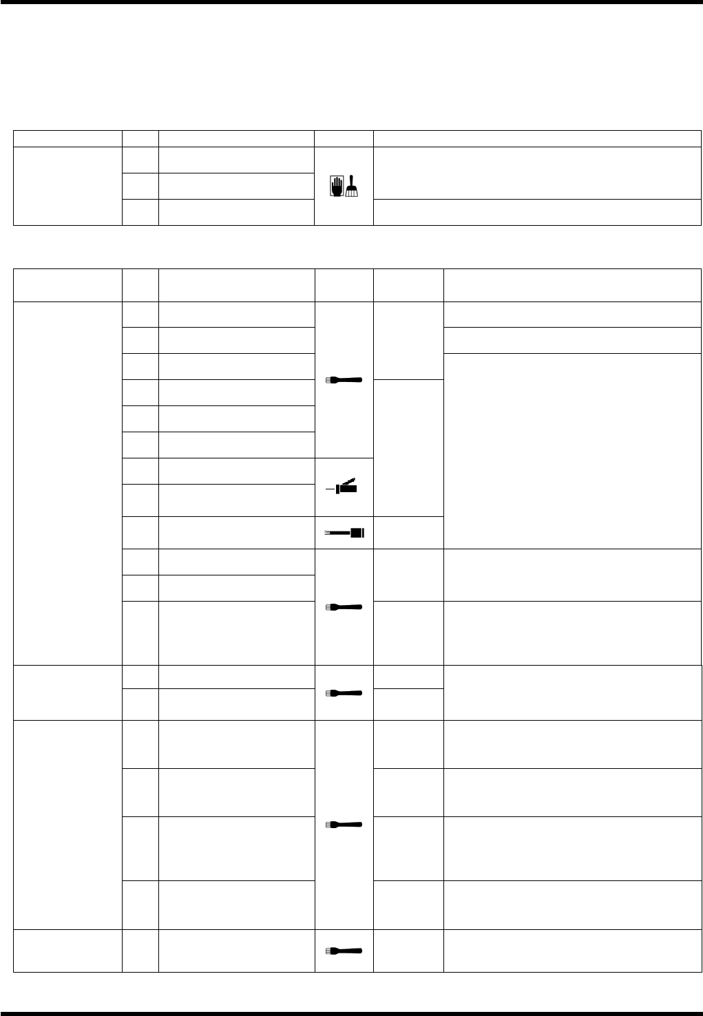
7.2.3 Biweekly Check Items
The following tables summarize the periodic inspection items that are to be performed every other week.
For the details of inspection positions and lubrication method, refer to the subsequent sections.
Numbers in the Unit column show the relevant sections to be referred to.
Inspection (Every other week)
Unit No. Item Task Description
c. Ball screw
d. LM guide
Remove dirt or dust.
7.9.1
Upper Anvil
e. Waste intake
Remove any wastes.
Oiling (Every other week)
Unit No. Item Task
Oiling
volume
Description
1. Pusher Position: Up/down sliding surfaces
2. Insertion guide
3. Slide cam
0.05 cm
3
4. Guide
5. Guide base
6. Roller and slide cam
7. Pin and block lever
8.
Pin, lever and guide
base
0.02 cm
3
9.
Pin, bracket and
bending die
0.01 cm
3
Position: Sliding surface
10. Pusher
11. Insertion guide
0.02 cm
3
Position: Sliding surface in the direction
of pitch
7.6.2
Insertion Unit
12.
Fitting surfaces
between the insertion
guide and the slide
cam
0.01 cm
3
Position: Fitting surface
1. Ball screw 0.5 cm
3
7.6.3
Insertion Unit
Drive
2. LM guide (2 areas)
0.1 cm
3
each
Apply grease after removing all foreign
matters.
2.
Sliding surfaces
between the cam
follower and the rod
0.5 cm
3
4.
Sliding surfaces
between the shaft and
the block.
0.1 cm
3
5.
Sliding surfaces
between the rod and
the bush (Insertion
Head) (2 areas)
0.1 cm
3
each
7.6.4
JW Head Unit
(Drive)
(Option)
6.
Sliding surfaces
between the shaft and
the cam follower
0.1 cm
3
7.6.5
JW Head Unit
(Option)
1.
Jumper wire setting
knob
0.5 cm
3
each
Position: Sliding surface
AV131
MAINTENANCE MANUAL
7.2 Periodic Inspection Items
D79MEC-Z0-020-A0
7.2-4
Unit No. Item Task
Oiling
volume
Description
1.
LM guide for 90°
rotation chuck
(4 areas)
2.
LM guide for insertion
unit transfer
3.
LM guide for sliding the
chuck vertically
4.
LM guide for sliding the
chuck back and forth
0.1 cm
3
Position: Sliding surface
5.
Sliding surface of the
groove cam
Position: Grease nipple
6. Lever support
7.
Lever support
(2 areas)
7.8.2
Transfer Chuck
8.
Sliding surfaces
between the pin and
the chuck (4 areas)
0.5 cm
3
Position: Sliding surface
1. Lever support
2. Roller (2 areas)
1 to 2
drops
Position: Support unit
3. LM guide (2 areas) 0.1 cm
3
7.9.1
Upper Anvil
4. Ball screw 0.5 cm
3
Position: Sliding surface
1.
Sliding surfaces
between the guide and
the slider (left/right)
Inject grease through the oil holes (× 4)
using a grease gun fitted with a P-type
attachment. (from Z axis side on the
back)
2. Bush support pin
0.3 cm
3
each
Position: Grease nipple
3. Roller follower
0.5 cm
3
each
Position: Roller surface
4.
Sliding surface of the
roller follower
0.5 cm
3
7.10.1
Tape Cutter
5.
Sliding surfaces
between the guide and
the roller follower
(top/bottom)
0.3 cm
3
each
AV131
MAINTENANCE MANUAL
7.2 Periodic Inspection Items
D79MEC-Z0-020-A0
7.2-5
7.2.4 Monthly Check Items
The following tables summarize the periodic inspection items that are to be performed monthly.
For the details of inspection positions and lubrication method, refer to the subsequent sections.
Numbers in the Unit column show the relevant sections to be referred to.
Inspection (Monthly)
Unit No. Item Task Description
a. Roller Make sure that the roller turns smoothly.
7.7.1
Transfer Arm
Interlock Unit
b.
Transfer arm interlock
unit
Make sure that the unit is not worn, and moves
smoothly without abnormal noises.
a. LM guide
7.8.1
Part Supply Unit
b. Ball screw shaft
Remove dirt or dust.
Protective glass
7.9.3
Automatic
Correction Unit
a.
Projector
Remove oil or dust.
Oiling (Monthly)
Unit No. Item Task
Oiling
volume
Description
1. Ball screw (X)
7.3.1
X-Y Table
2. Ball screw (Y)
3 cm
3
each
Position: Thread
1.
Sliding surfaces
between the guide and
the rod
0.1 cm
3
3. Cam surface 0.5 cm
3
Position: Periphery
7.
LM guide (2 units: front
and rear)
0.6 cm
3
each
Position: Rail surface
7.6.4
JW Head Drive
Unit (Option)
8.
Contacting surfaces
between the shaft and
the pusher
0.05 cm
3
7.6.5
JW Head Unit
(Option)
2. Worm gear
0.5 cm
3
each
Position: Grease nipple
7.6.6
Main Unit
1. Cam surface 0.5 cm
3
Position: Cam surface
1.
Sliding surface of the
cam follower (5 areas)
2.
Rotating bearing of the
shaft
Set cycle timer to 262° for the
lubrication.
3.
Sliding surfaces
between the slider and
the frame
4.
Sliding surfaces
between the shaft and
the bush
Position: Grease nipple
5.
Sliding surfaces
between the shaft and
the bush (2 areas)
6.
Sliding surfaces of the
shaft, bush and guide
(3 areas)
7.
Sliding surface of the
slider
7.6.1
Insertion Head
8. Trapezoidal screw
0.5 cm
3