Maintenance Manual.pdf - 第148页
AV131 MAINTENANCE MANUAL 7.6 I nserti on Head Un i t D79MEC- Z1-M 00-A0 7.6- 1 7.6. Insertion H ead Uni t D79MEC -Z1- M00 -A0 7.6. 1 Inserti on Head Unit No. N6100552012A A 4. Sl idi ng surf aces between t he shaf t and …

AV131
MAINTENANCE MANUAL
7.5 PCB Positioning Unit
D79MEC-Z3-400-A0
7.5-2
AV131
MAINTENANCE MANUAL
7.6 Insertion Head Unit
D79MEC-Z1-M00-A0
7.6-1
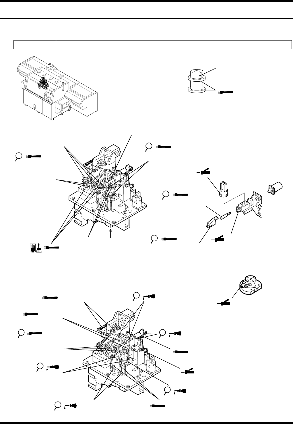
7.6. Insertion Head Unit
D79MEC-Z1-M00-A0
7.6.1 Insertion Head
Unit No. N6100552012AA
4. Sliding surfaces
between the shaft
and the bush
Detailed view of C
Detailed view of A
Bolt
1. Sliding surface of the
cam follower
A (3 positions)
B
5. Sliding surfaces between the
shaft and the bush (2 areas)
A
6. Sliding surfaces of the
shaft, bush and guide (3 areas)
10.Sliding surfaces
between the guide
and the rod
2. Rotating bearing of the
shaft
3. Sliding surfaces between
the slider and the frame
Detailed view of B
8. Trapezoidal screw
7. Sliding surface of
the slider
9. Sliding surfaces between
the shaft and the bush
13. Spring
14. Spring
11. Spring
12. Spring
17. Pin
1. Sliding surface of
the cam follower
18. Pin
16. Pin
15. Pin
19. Pin

AV131
MAINTENANCE MANUAL
7.6 Insertion Head Unit
D79MEC-Z1-M00-A0
7.6-2
Oiling
Period No. Item Task
Oiling
volume
Description
1.
Sliding surface of the
cam follower (5 areas)
2.
Rotating bearing of the
shaft
Set cycle timer to 262° for the lubrication.
3.
Sliding surfaces
between the slider and
the frame
4.
Sliding surfaces
between the shaft and
the bush
Position: Grease nipple
5.
Sliding surfaces
between the shaft and
the bush (2 areas)
6.
Sliding surfaces of the
shaft, bush and guide
(3 areas)
7.
Sliding surface of the
slider
8. Trapezoidal screw
9.
Sliding surfaces
between the shaft and
the bush
0.5 cm
3
Position: Grease nipple
Monthly
10.
Sliding surfaces
between the guide and
the rod
0.1 cm
3
11. Spring (x 2)
12. Spring (x 2)
13. Spring (x 2)
14. Spring
15. Pin (2 positions)
16. Pin (2 positions)
17. Pin (2 positions)
18. Pin (2 positions)
3
months
19. Pin (2 positions)
0.5 cm
3