Maintenance Manual.pdf - 第159页
AV131 MAINTENANCE MANUAL 7.8 Par t Supply Unit D79MEC- Z5-000- A0 7.8- 2 Inspection Perio d No . Item T ask Descrip ti on a. LM gui de Mont hly b. B all scr ew sh a f t Re m o ve d irt or du s t. Oiling Perio d No . …
AV131
MAINTENANCE MANUAL
7.8 Part Supply Unit
D79MEC-Z5-000-A0
7.8-1
7.8. Part Supply Unit
D79MEC-Z5-000-A0
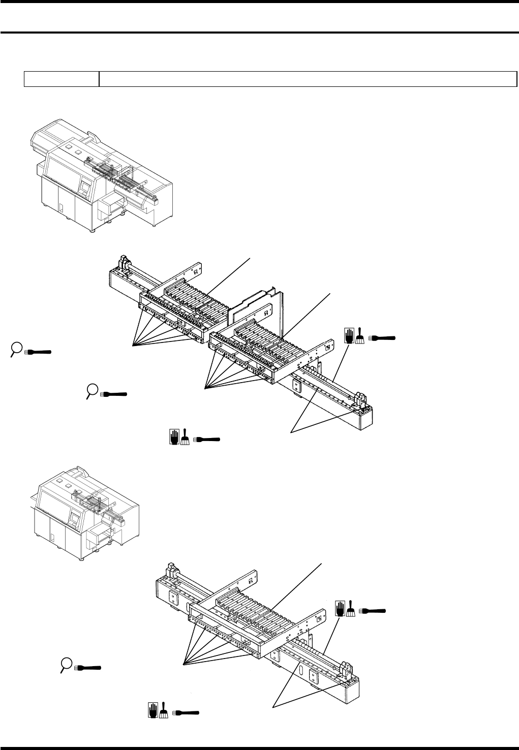
7.8.1 Part Supply Unit
Unit No. N610064467AA / N610060958AA
120 Inputs
60 Inputs
Feeder frame
Feeder frame
2. Cam follower
a / 1. LM guide
b / 3. Ball screw shaft
2. Cam follower
Feeder frame
a / 1. LM guide
2. Cam follower
b / 3. Ball screw shaft
AV131
MAINTENANCE MANUAL
7.8 Part Supply Unit
D79MEC-Z5-000-A0
7.8-2
Inspection
Period No. Item Task Description
a. LM guide
Monthly
b. Ball screw shaft
Remove dirt or dust.
Oiling
Period No. Item Task
Oiling
volume
Description
1. LM guide (x 2)
2.0 cm
3
each
120
inputs
1.0 cm
3
each
60
inputs
Position: Rail surface
2.
Cam follower
120 inputs (x 12)
60 inputs (x 6)
1.9 cm
3
each
Position: Roller surface
3
months
3. Ball screw shaft
120
inputs
80 cm
3
60
inputs
50 cm
3
Position: Sliding surface
AV131
MAINTENANCE MANUAL
7.8 Part Supply Unit
D79MEC-Z5-000-A0
7.8-3
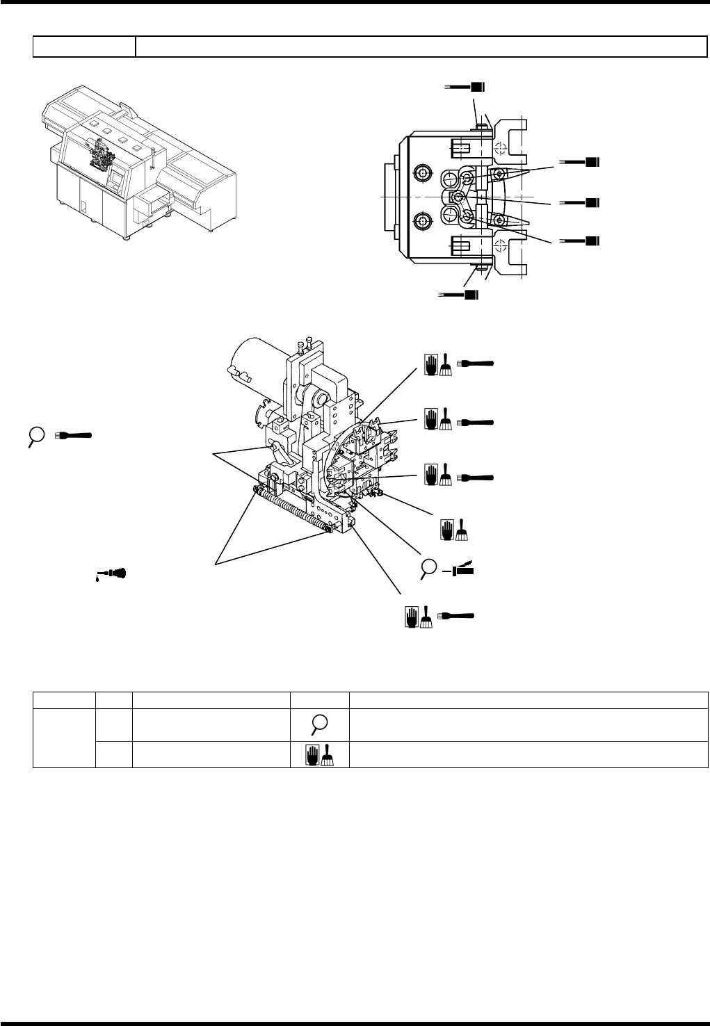
7.8.2 Transfer Chuck
Unit No. N610052073AA
Inspection
Period No. Item Task Description
a. Groove cam
Make sure that the groove cam slides smoothly and
there is no abnormal noise at the joint.
Daily
b. Piston & chuck
Remove dirt or dust.
4. LM guide for sliding the
chuck back and forth
1. LM guide for 90°
rotation chuck
2. LM guide for insertion unit
transfer
3. LM guide for sliding the
chuck vertically
10. Spring support pin
b. Piston & chuck
a. /5. Sliding surface of the
groove cam
9. Sliding surface of
the cam follower
8. Sliding surfaces between the
pin and the chuck (4 areas)
8. Sliding surfaces between the
pin and the chuck (4 areas)
7. Lever support
6. Lever support
7. Lever support