Maintenance Manual.pdf - 第162页
AV131 MAINTENANCE MANUAL 7.9 Anv il Unit D79MEC- Z4-400- A0 7.9- 1 7.9. A nvil Unit D79MEC -Z4- 4 00- A0 7.9. 1 Upper A nvil Unit No. N610052020A A Inspection Perio d No . Item T ask Descrip ti on Make sure t hat t he …

AV131
MAINTENANCE MANUAL
7.8 Part Supply Unit
D79MEC-Z5-000-A0
7.8-4
Oiling
Period No. Item Task
Oiling
volume
Description
1.
LM guide for 90°
rotation chuck
(4 areas)
2.
LM guide for insertion
unit transfer
3.
LM guide for sliding the
chuck vertically
4.
LM guide for sliding the
chuck back and forth
0.1 cm
3
Position: Sliding surface
5.
Sliding surface of the
groove cam
Position: Grease nipple
6. Lever support
7.
Lever support
(2 areas)
Every
other
week
8.
Sliding surfaces
between the pin and
the chuck (4 areas)
9.
Sliding surface of the
cam follower
Position: Sliding surface
3
months
10. Spring support pin
0.5 cm
3
AV131
MAINTENANCE MANUAL
7.9 Anvil Unit
D79MEC-Z4-400-A0
7.9-1
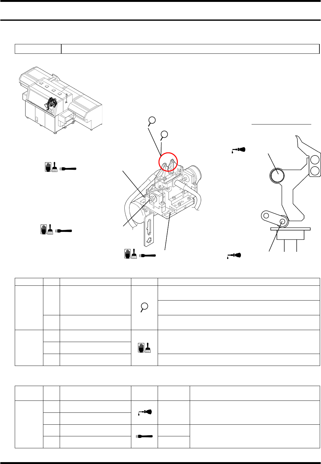
7.9. Anvil Unit
D79MEC-Z4-400-A0
7.9.1 Upper Anvil
Unit No. N610052020AA
Inspection
Period No. Item Task Description
Make sure that the tip of the cutter & clincher blade is
not worn or damaged.
a. Cutter & clincher
Make sure that the cutter & clincher moves smoothly
without abnormal noises.
Daily
b. Clinch base
Make sure that the tip of the clinch base blade is not
worn or damaged.
c. Ball screw
d. LM guide
Remove dirt or dust.
Every
other
week
e. Waste intake
Remove any wastes.
Oiling
Period No. Item Task
Oiling
volume
Description
1. Lever support
2. Roller (2 areas)
1 to 2
drops
Position: Support unit
3. LM guide (2 areas) 0.1 cm
3
Every
other
week
4. Ball screw
0.5 cm
3
Position: Sliding surface
2. Roller
a. Cutter & clincher
d / 3. LM guide
b. Clinch base
1. Lever support
c / 4. Ball screw
d / 3. LM guide
Detailed view of lever
AV131
MAINTENANCE MANUAL
7.9 Anvil Unit
D79MEC-Z4-400-A0
7.9-2
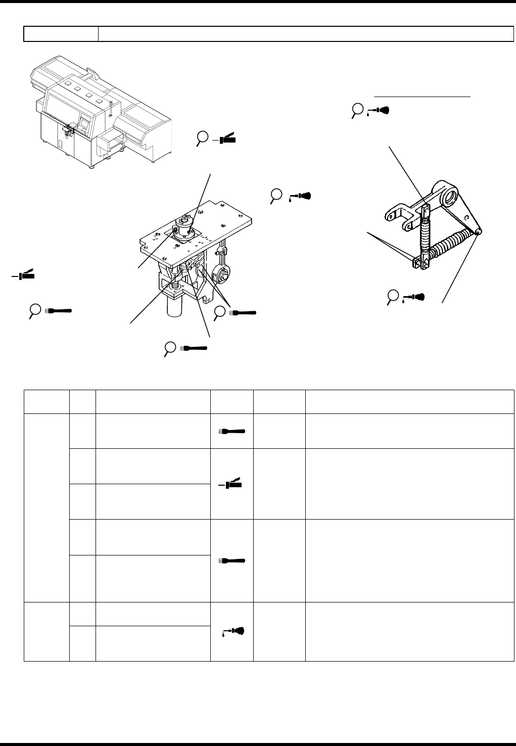
7.9.2 Lower Anvil
Unit No. N610052019AA
Oiling
Period No. Item Task
Oiling
volume
Description
1.
Sliding surfaces
between the roller
follower and the cam
0.5 cm
3
Position: Cam surface
2.
Sliding surfaces
between the flange
and the lower anvil
3.
Engagement between
the gear and the shaft
gear
0.3 cm
3
Position: Grease nipple
4.
Sliding surfaces
between the cam
follower and the nut
Monthly
5.
Sliding surfaces
between the cam
follower and the roller
guide
0.1 cm
3
Position: Roller surface
6.
Rotating sliding
surface of the pin
3
months
7.
Rotating sliding
surface between the
shaft and the pin
1 to 2
drops
Grease up at assembly
3. Engagement between
the gear and the shaft
gear
5. Sliding surfaces between
the cam follower and the
roller guide
4. Sliding surfaces between the
cam follower and the nut
1. Sliding surfaces
between the roller
follower and the cam
2. Sliding surfaces between the
flange and the lower anvil
Detailed view of lever
6. Rotating sliding surface
of the pin
6. Rotating sliding surface
of the pin
7. Rotating sliding surface
between the shaft and
the pin