Maintenance Manual.pdf - 第179页
AV131 MAINTENANCE MANUAL 8.1 Anv il Unit D79MEC-W 4-400- A0 8.1- 2
AV131
MAINTENANCE MANUAL
8.1 Anvil Unit
D79MEC-W4-400-A0
8.1-1
8.1. Anvil Unit
D79MEC-W4-400-A0
8.1.1 Anvil Unit Consumable Parts Replacement
Unit No. N610052020AA
8.1.1 Anvil Unit Consumable Parts
Replacement
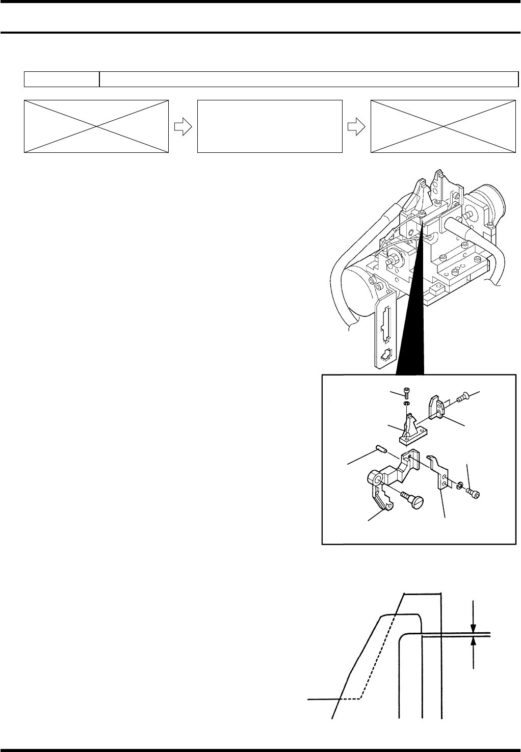
Anvil Unit Consumable Parts Replacement
7.
1. Turn the power OFF.
2. Disconnect the tube and connector from the anvil.
3. Remove the anvil unit from the machine.
4. Loosen the clinch base bolts (2 pcs.) and remove the
clinch base.
5. Loosen the flush bolts (2 pcs.) and remove the cover.
6. Loosen the clinch base bolts (2 pcs.) and the flush bolts (2
pcs.) from the other clinch base and remove.
7. Attach the cover to the new clinch base and tighten the
flush bolts (2 pcs.).
8. Loosen the cutter & clincher bolts (2 pcs.) and remove the
cutter & clincher of one side.
9. Attach a new cutter & clincher.
10. Tighten the cutter & clincher bolts (2 pcs.).
11. Attach a new clinch base and tighten the bolts (2 pcs.). Fit
the clinch base to the block and loosen the bolts.
12. Replace the cutter & clincher and clinch base of the other
side similarly.
13. Check the clearance between the clinch base and the cutter & clincher.
=SPECIFICATION=
Clearance: 0.01 - 0.03 mm
14. Tighten the cutter & clincher bolts (2 pcs.).
0.01 -
0.03 mm
Clinch base
Clinch base
bolt
Pin
Lever
Cutter & clincher
Cutter &
clincher bolt
Cover
Flush
bolt

AV131
MAINTENANCE MANUAL
8.1 Anvil Unit
D79MEC-W4-400-A0
8.1-2
AV131
MAINTENANCE MANUAL
8.2 Insertion Head Unit
D79MEC-W1-M00-A0
8.2-1
8.2. Insertion Head Unit
D79MEC-W1-M00-A0
8.2.1 Insertion Unit Consumable Parts Replacement
Unit No. 1087110000
8.2.1 Insertion Unit Consumable
Parts Replacement
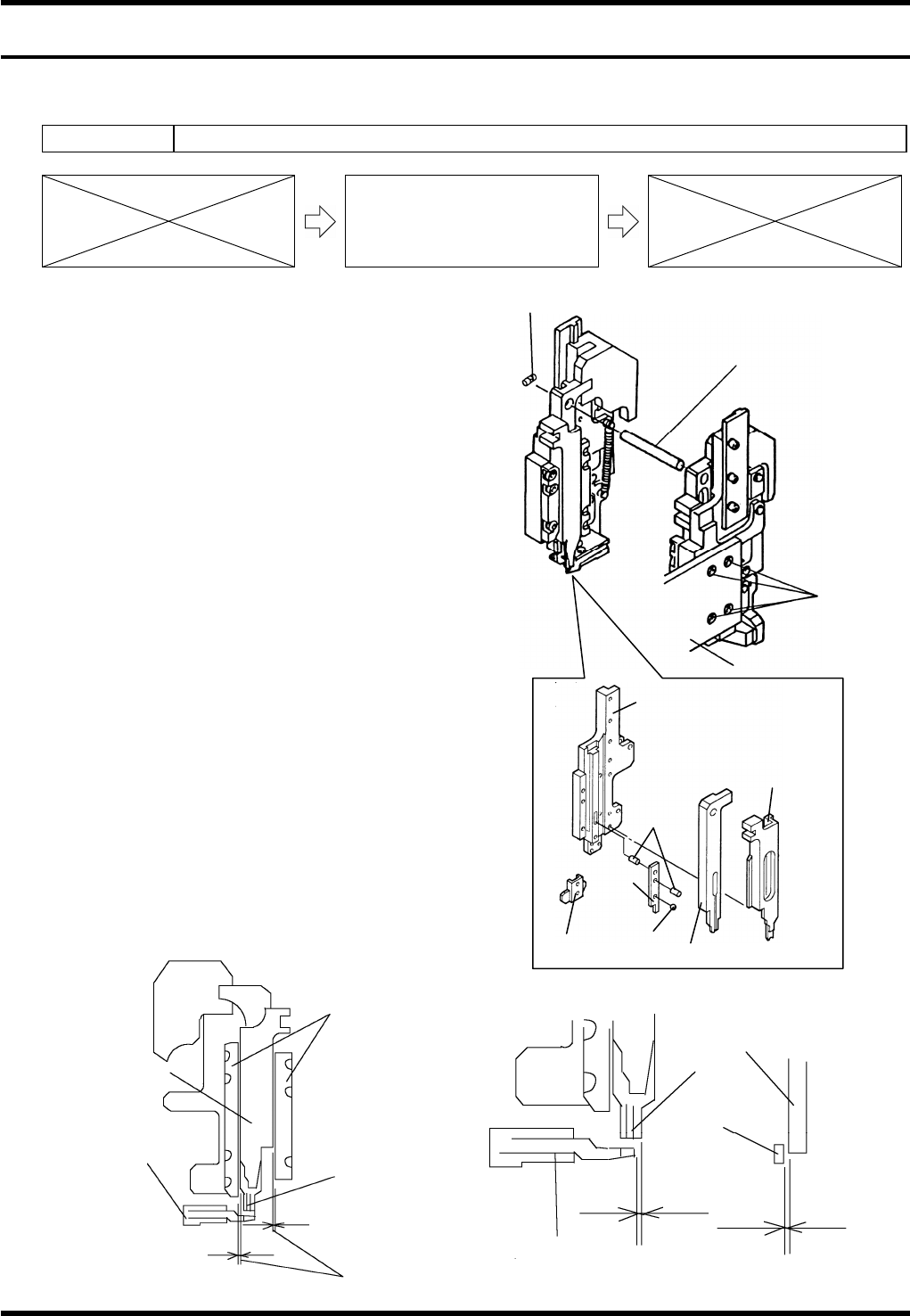
Insertion Unit Consumable Parts
Replacement
8.
1. Turn the power ON and return to origin.
2. Rotate the handwheel to set the cycle timer to 0°.
3. Turn the power OFF.
4. Remove the bolts (4 pcs.).
5. Loosen the set screw and pull out the shaft.
6. Remove the insertion unit.
7. Replace the insertion guide, cutter and pusher.
8. Check the clearance between the pusher and guide
plates.
=SPECIFICATION=
Clearance: 0.01 - 0.03 mm
9. Check the clearance between the insertion guide
and bending die.
=SPECIFICATION=
Clearance: 0.01 - 0.03 mm
10. Check the gap between the insertion guide side
face and bending die end face.
=SPECIFICATION=
Gap: 0 ± 0.02 mm
Pusher
Bending die
Clearance
Insertion
guide
Guide plate
Insertion
guide
Bending
die
Bending die
Gap
Clearance
Bolt
Set screw
Shaft
Guide base
Insertion guide
Cutter
Pin
Steel ball
Pusher
Insertion unit drive
Cutter