Maintenance Manual.pdf - 第182页
AV131 MAINTENANCE MANUAL 8.2 I nserti on Head Un i t D79MEC-W 1-M 00-A0 8.2- 3 8.2. 2 Inserti on Guide Hei ght A djustm ent Unit No. N610052012A A / 1087110000 / N610052020AA 8.2 .2 I ns erti on G ui d e H eight Adjustme…
AV131
MAINTENANCE MANUAL
8.2 Insertion Head Unit
D79MEC-W1-M00-A0
8.2-2
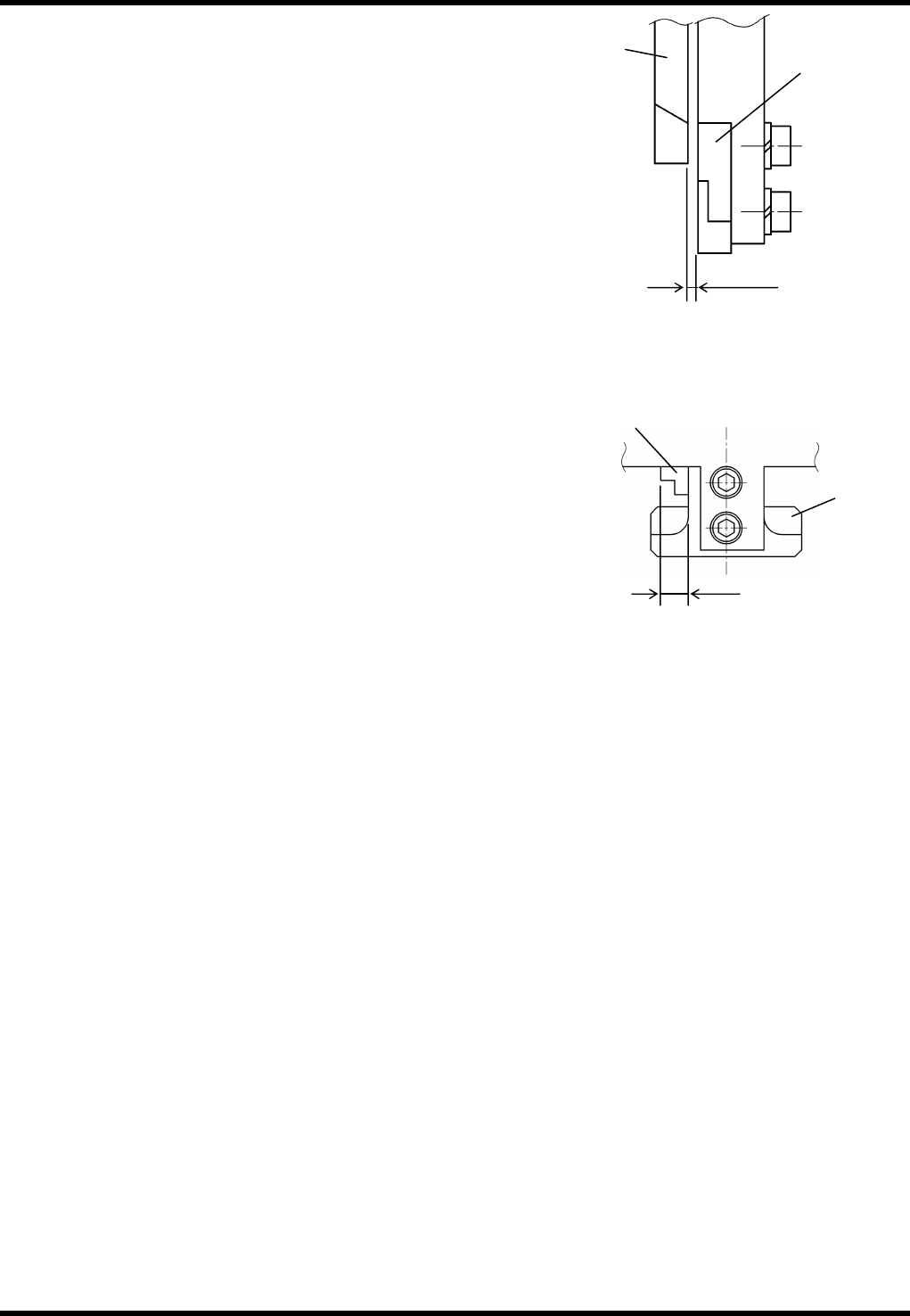
11. Check the clearance between the fixed blade and movable
blade.
=SPECIFICATION=
Clearance: 0.00 - 0.03 mm
12. Check the gap between the fixed blade side face and
movable blade side face.
=SPECIFICATION=
Gap: 3.58 - 3.62 mm
=REMARKS=
Be sure to replace the steel ball and pins if they are
worn or damaged.
Fixed blade
Movable
blade
Clearance
Gap
Fixed
blade
Movable
blade
AV131
MAINTENANCE MANUAL
8.2 Insertion Head Unit
D79MEC-W1-M00-A0
8.2-3
8.2.2 Insertion Guide Height Adjustment
Unit No. N610052012AA / 1087110000 / N610052020AA
8.2.2 Insertion Guide Height
Adjustment
=PREPARATION=
1. PCB 1.6 mm thick
Insertion Guide Height Adjustment
9.
1. Turn the power ON and return to origin.
2. Check that the X-Y table rail is not located below the
insertion head.
If located, move the X-Y table rail to a position where it
will not interfere with the head even when the head is
lowered.
3. Open the front cover.
4. Turn the maintenance switch ON.
5. Press “START” on the main control panel.
Make sure the red lamp of the signal tower flashes.
6. Turn the “SERVO” switch OFF.
7. Turn the “HEAD BRAKE” switch OFF (RELEASE).
8. Rotate the handwheel to set the cycle timer to 233°.
9. Turn the “HEAD BRAKE” switch ON (LOCK).
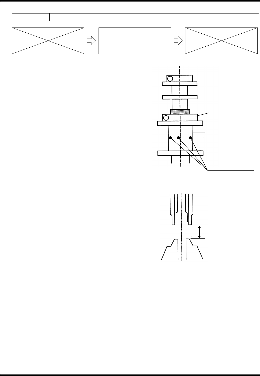
10. Combine thickness gauges properly and check that the gap
between the head and anvil is within the range of PCB
thickness + 0.25.
=REMARKS=
Check the clearance at two consecutive cycles because
a 2-cycle cam is incorporated.
11. If there is some clearance or if the PCB is being pressed down, loosen the nut bolt and rotate the slide
block to adjust the insertion guide height. (Insert an Allen wrench in the hole of the slide block and rotate it
to make adjustment.)
12. When adjustment is completed, tighten the nut bolt.
Nut
Slide block
Holes for rotating
slide block
(PCB thickness +0.25)
±
0.05
AV131
MAINTENANCE MANUAL
8.2 Insertion Head Unit
D79MEC-W1-M00-A0
8.2-4
8.2.3 Rotary Chuck and Centering Chuck Replacement
Unit No. N610052073AA
8.2.3 Rotary Chuck and Centering
Chuck Replacement
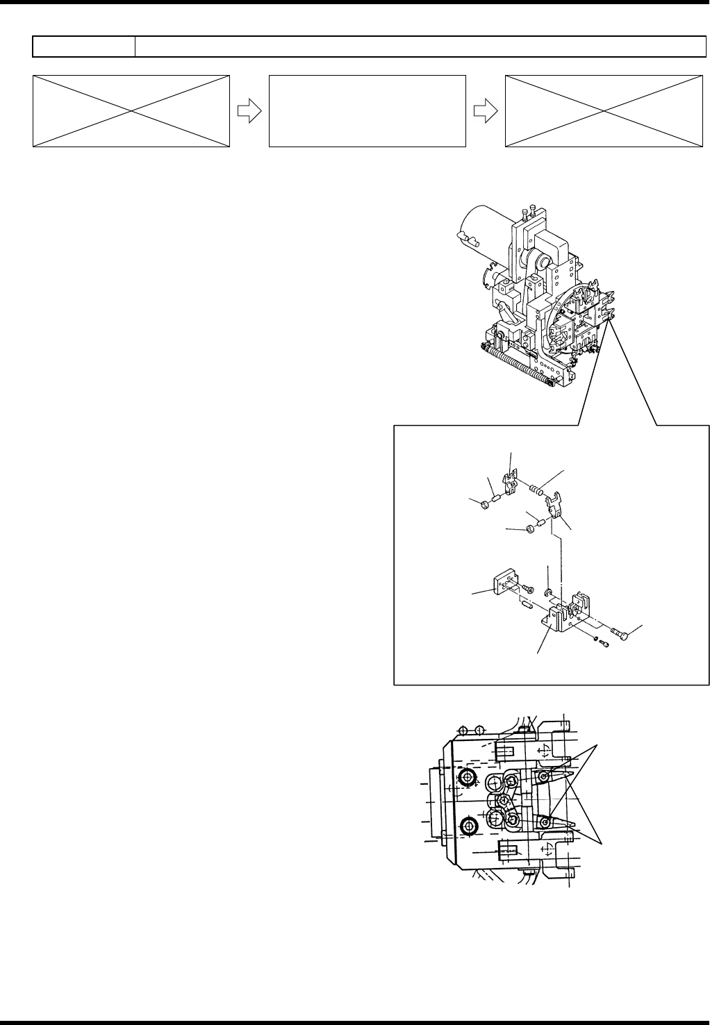
Rotary Chuck Replacement
10.
1. Turn the power OFF.
2. Move the chuck unit toward you.
3. Remove the E-ring and pull the pins out.
4. Pull the chuck out.
=REMARKS=
Be careful not to drop the spring at this step.
5. Replace the chuck.
6. Put the spring inside of the hole of the chuck.
7. Apply thin coat of grease to the sliding part that
fits in the chuck body.
8. Close the chuck with hands and check whether
the chuck is opened by the force of the spring.
9. Insert the chucks.
10. Insert the pin and fix with the E-ring.
Centering Chuck Replacement
11.
1. Turn the power OFF.
2. Move the chuck unit toward you.
3. Loosen the bolts and remove the centering
chuck.
4. Replace the centering chuck.
5. Tighten the bolts.
Collar
Chuck (L)
Chuck (R)
Cylinder block
Spring
Pin
Roller
Pin
Pin
E-ring
Roller
Centering chuck
Bolt