Maintenance Manual.pdf - 第184页
AV131 MAINTENANCE MANUAL 8.3 Par t Supply Unit D79MEC-W 5-000- A0 8.3- 1 8.3. Part Suppl y Unit D79MEC -W 5 -000-A0 8.3. 1 Component Detection Sensor A djustm ent Unit No. N610052014A A 8.3 .1 C omp on en t D et e c t io…
AV131
MAINTENANCE MANUAL
8.2 Insertion Head Unit
D79MEC-W1-M00-A0
8.2-4
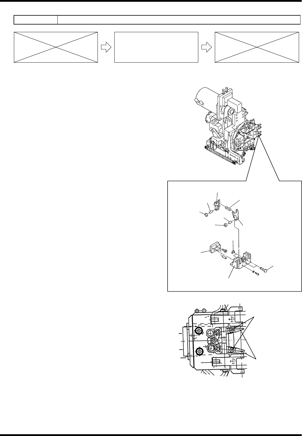
8.2.3 Rotary Chuck and Centering Chuck Replacement
Unit No. N610052073AA
8.2.3 Rotary Chuck and Centering
Chuck Replacement
Rotary Chuck Replacement
10.
1. Turn the power OFF.
2. Move the chuck unit toward you.
3. Remove the E-ring and pull the pins out.
4. Pull the chuck out.
=REMARKS=
Be careful not to drop the spring at this step.
5. Replace the chuck.
6. Put the spring inside of the hole of the chuck.
7. Apply thin coat of grease to the sliding part that
fits in the chuck body.
8. Close the chuck with hands and check whether
the chuck is opened by the force of the spring.
9. Insert the chucks.
10. Insert the pin and fix with the E-ring.
Centering Chuck Replacement
11.
1. Turn the power OFF.
2. Move the chuck unit toward you.
3. Loosen the bolts and remove the centering
chuck.
4. Replace the centering chuck.
5. Tighten the bolts.
Collar
Chuck (L)
Chuck (R)
Cylinder block
Spring
Pin
Roller
Pin
Pin
E-ring
Roller
Centering chuck
Bolt
AV131
MAINTENANCE MANUAL
8.3 Part Supply Unit
D79MEC-W5-000-A0
8.3-1
8.3. Part Supply Unit
D79MEC-W5-000-A0
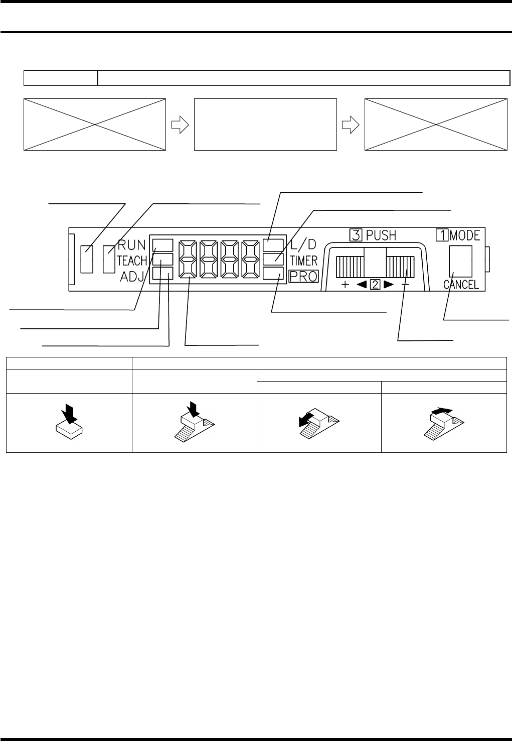
8.3.1 Component Detection Sensor Adjustment
Unit No. N610052014AA
8.3.1 Component Detection Sensor
Adjustment
Component Detection Sensor Adjustment
MODE switch Jog switch
Turn
Press Press
‘+’ side ‘-’ side
12.
1. Press the <MODE> switch to change the mode to ‘L/D’. Check that ‘D-ON’ appears on the digital display.
(If not, turn the jog switch until ‘D-ON’ is displayed.)
2. Press the <MODE> switch to change the mode to ‘TEACH’.
3. With a work present (blocking the component detector), press the jog switch for more than 0.5 seconds.
=REMARKS=
Use a metal scale, etc., as a work for adjustment to block the light completely.
4. When “AUTO” appears on the digital display, release the jog switch.
5. The judgment on the stability of sensing is displayed.
(If stable sensing is enabled, “GOOD” is displayed and “HARD” appears if not.)
=REMARKS=
When a component is within the sensing range, the stability indicator will turn ON.
13.
Operation indicator
(Orange)
Stability indicator (Green)
MODE indicator / L/D ON (Yellow)
MODE indicator / TIMER (Yellow)
MODE indicator / RUN (Green)
MODE indicator / TEACH (Yellow)
MODE indicator / ADJ (Yellow)
MODE indicator / PRO
(Yellow)
Digital display
Jog switch
MODE switch
AV131
MAINTENANCE MANUAL
8.3 Part Supply Unit
D79MEC-W5-000-A0
8.3-2
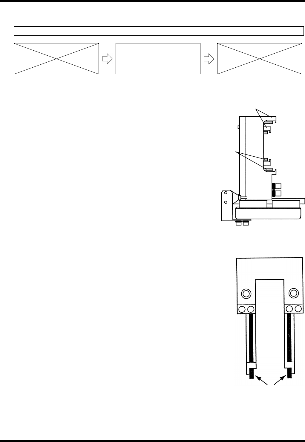
Sensor
8.3.2 Slide Chuck Block and Component Detection Sensor
Cleaning
Unit No. N610052073AA / N610052014AA
8.3.2 Slide Chuck Block and
Component Detection Sensor
Cleaning
Slide Chuck Block Cleaning
14.
1. Turn the power ON and return to origin.
2. Call up the “IO control” screen from the [Machine adjustment]
menu screen.
3. Turn [Slider forward] ON.
4. Turn [26 slider] [52 slider] ON/OFF and clean the slide chuck
block and piston with a cotton swab soaked in alcohol.
Component Detection Sensor Cleaning
15.
1. Turn the power ON and return to origin.
2. Move the part supply unit to the standby position.
3. Clean the sensors with a cotton swab soaked in alcohol.
Slide chuck
block
Piston