Maintenance Manual.pdf - 第185页
AV131 MAINTENANCE MANUAL 8.3 Par t Supply Unit D79MEC-W 5-000- A0 8.3- 2 Sensor 8.3. 2 Slide Chuck Block and Component Detection S ensor Cleani n g Unit No. N610052073A A / N610052014A A 8.3 .2 Sli d e C huc k Bl oc k an…
AV131
MAINTENANCE MANUAL
8.3 Part Supply Unit
D79MEC-W5-000-A0
8.3-1
8.3. Part Supply Unit
D79MEC-W5-000-A0
8.3.1 Component Detection Sensor Adjustment
Unit No. N610052014AA
8.3.1 Component Detection Sensor
Adjustment
Component Detection Sensor Adjustment
MODE switch Jog switch
Turn
Press Press
‘+’ side ‘-’ side
12.
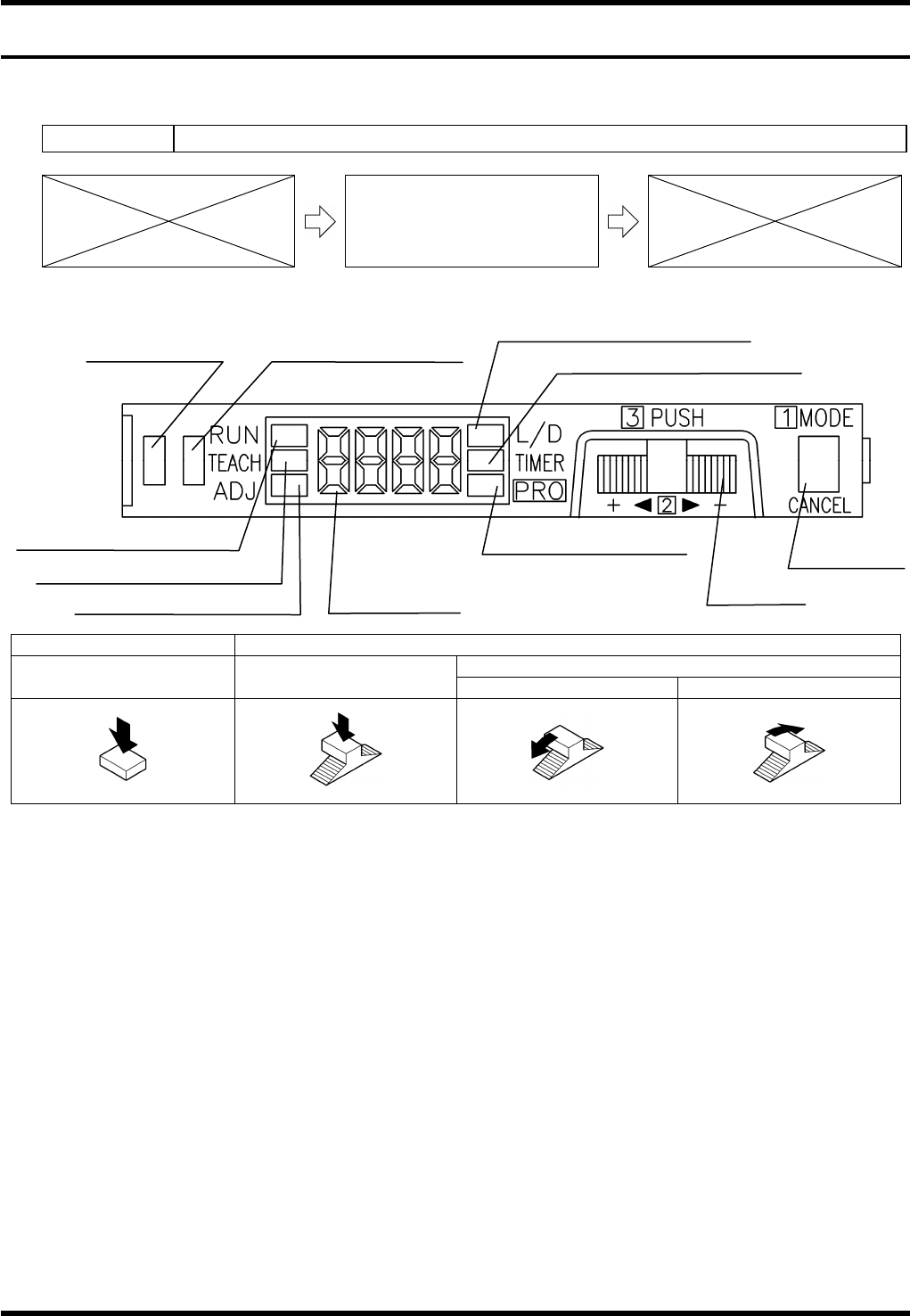
1. Press the <MODE> switch to change the mode to ‘L/D’. Check that ‘D-ON’ appears on the digital display.
(If not, turn the jog switch until ‘D-ON’ is displayed.)
2. Press the <MODE> switch to change the mode to ‘TEACH’.
3. With a work present (blocking the component detector), press the jog switch for more than 0.5 seconds.
=REMARKS=
Use a metal scale, etc., as a work for adjustment to block the light completely.
4. When “AUTO” appears on the digital display, release the jog switch.
5. The judgment on the stability of sensing is displayed.
(If stable sensing is enabled, “GOOD” is displayed and “HARD” appears if not.)
=REMARKS=
When a component is within the sensing range, the stability indicator will turn ON.
13.
Operation indicator
(Orange)
Stability indicator (Green)
MODE indicator / L/D ON (Yellow)
MODE indicator / TIMER (Yellow)
MODE indicator / RUN (Green)
MODE indicator / TEACH (Yellow)
MODE indicator / ADJ (Yellow)
MODE indicator / PRO
(Yellow)
Digital display
Jog switch
MODE switch
AV131
MAINTENANCE MANUAL
8.3 Part Supply Unit
D79MEC-W5-000-A0
8.3-2
Sensor
8.3.2 Slide Chuck Block and Component Detection Sensor
Cleaning
Unit No. N610052073AA / N610052014AA
8.3.2 Slide Chuck Block and
Component Detection Sensor
Cleaning
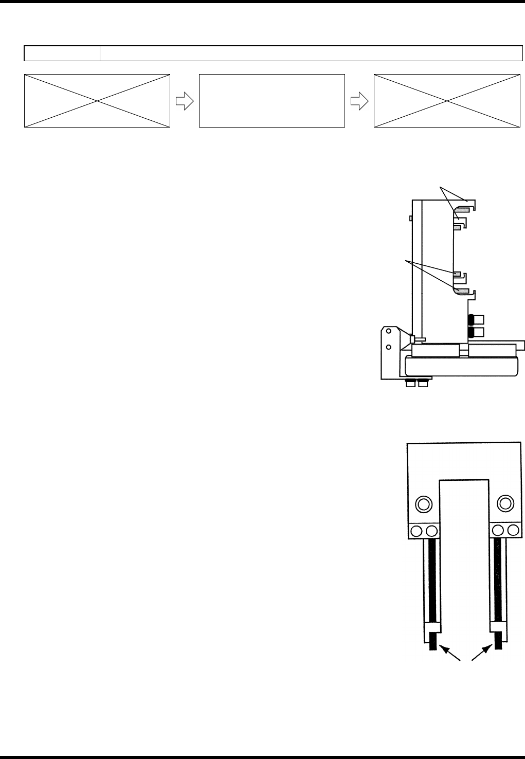
Slide Chuck Block Cleaning
14.
1. Turn the power ON and return to origin.
2. Call up the “IO control” screen from the [Machine adjustment]
menu screen.
3. Turn [Slider forward] ON.
4. Turn [26 slider] [52 slider] ON/OFF and clean the slide chuck
block and piston with a cotton swab soaked in alcohol.
Component Detection Sensor Cleaning
15.
1. Turn the power ON and return to origin.
2. Move the part supply unit to the standby position.
3. Clean the sensors with a cotton swab soaked in alcohol.
Slide chuck
block
Piston
AV131
MAINTENANCE MANUAL
8.4 Cutter Unit
D79MEC-W5-200-A0
8.4-1
8.4. Cutter Unit
D79MEC-W5-200-A0
8.4.1 Tape Cutter Replacement Adjustment
Unit No. N610052014AA
8.4.1 Tape Cutter Replacement
Adjustment
=PREPARATION=
1. Dial gauge
Tape Cutter Replacement Adjustment
16.
1. Turn the power ON and return to origin.
2. Turn the <SERVO> switch OFF.
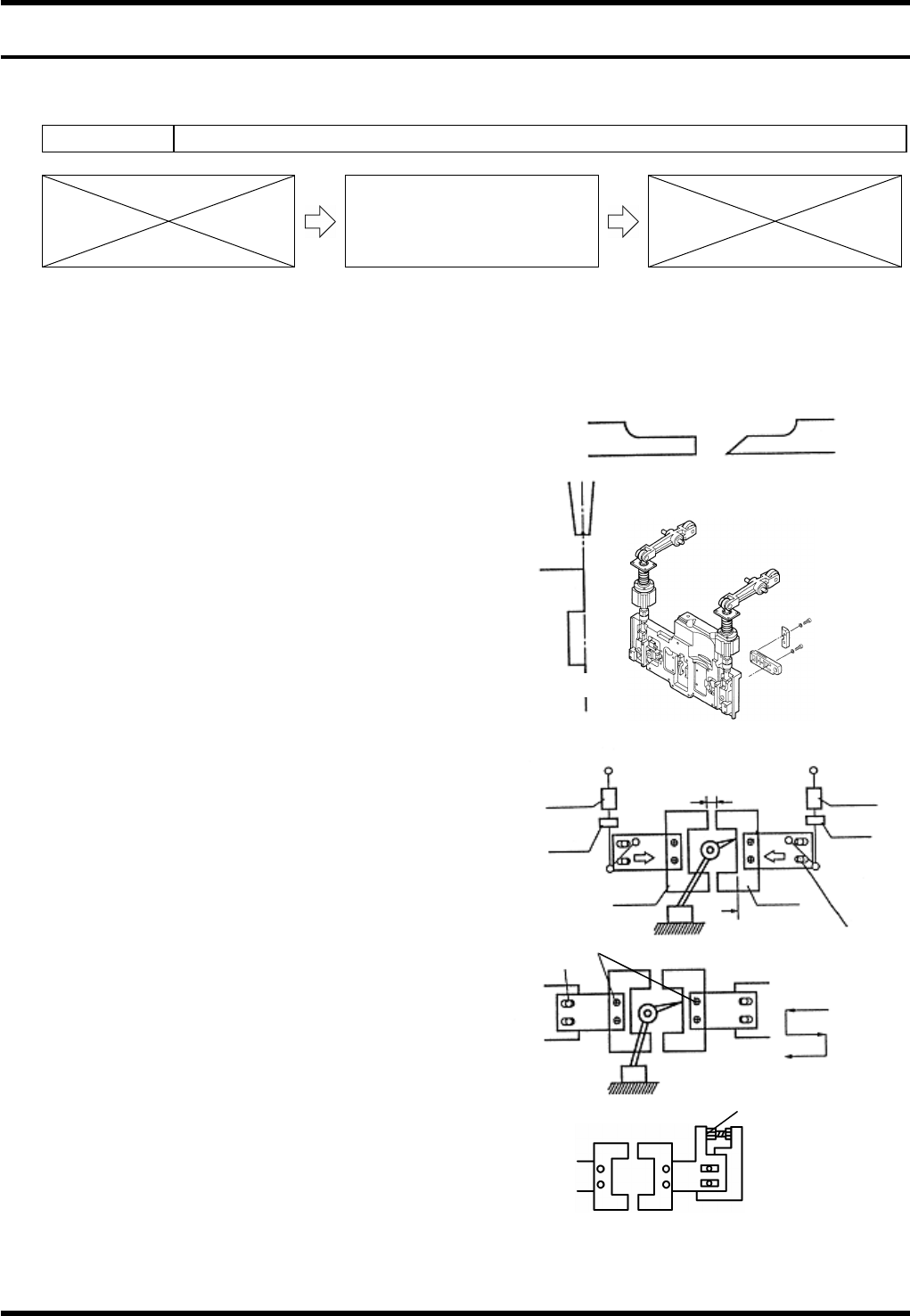
3. Loosen bolt (a) (4 pcs.).
4. Remove the cutters. (Blades A and B)
5. Loosen the bolts (b) and (c) fastening the slider.
6. Move the sliders to both sides.
7. Attach blade A.
8. Rotate the handwheel to set the cycle timer to
around 324°. (The blade A moves forward while
the handwheel is being rotated.)
9. Adjust the slider so that the blade A is in line with
the T- axis chuck (closed).
Refer to figure (a).
10. Tighten the bolt (b) to fix the slider.
11. Rotate the handwheel to move the cycle timer
back and forth between 295 - 340° and check
again.
12. Reattach the blade B and rotate handwheel to
set the cycle timer to 324°.
13. Shift the slider to allow the blade B to touch the
blade A, then tighten the bolt (c) temporarily.
14. Remove the blade A.
15. Set the dial gauge to the surface A and zero the
dial gauge.
Chuck
Cutter blade
Z axis side
Front side
AB
Drive-in amount
0.1 - 0.3 mm
Air damper
cylinder
Nut B
Bolt (c)
Blade B
Surface A
Blade A
Nut A
A
ir damper
cylinder
Bolt (a)
Bolt (b)
CT: 324°
CT: 324°
CT: 235°
Cutter
Slider
Adjustment bolt
Fig. (a)