Maintenance Manual.pdf - 第187页
AV131 MAINTENANCE MANUAL 8.4 Cut ter Unit D79MEC-W 5-200- A0 8.4- 2 16. Rotate t he ad j ust bol t to mo v e the sli der 0.1 m m to t he left and ti ghten the bolt ( c) to s ecure t he blade A . (Measure t he m o v ement…
AV131
MAINTENANCE MANUAL
8.4 Cutter Unit
D79MEC-W5-200-A0
8.4-1
8.4. Cutter Unit
D79MEC-W5-200-A0
8.4.1 Tape Cutter Replacement Adjustment
Unit No. N610052014AA
8.4.1 Tape Cutter Replacement
Adjustment
=PREPARATION=
1. Dial gauge
Tape Cutter Replacement Adjustment
16.
1. Turn the power ON and return to origin.
2. Turn the <SERVO> switch OFF.
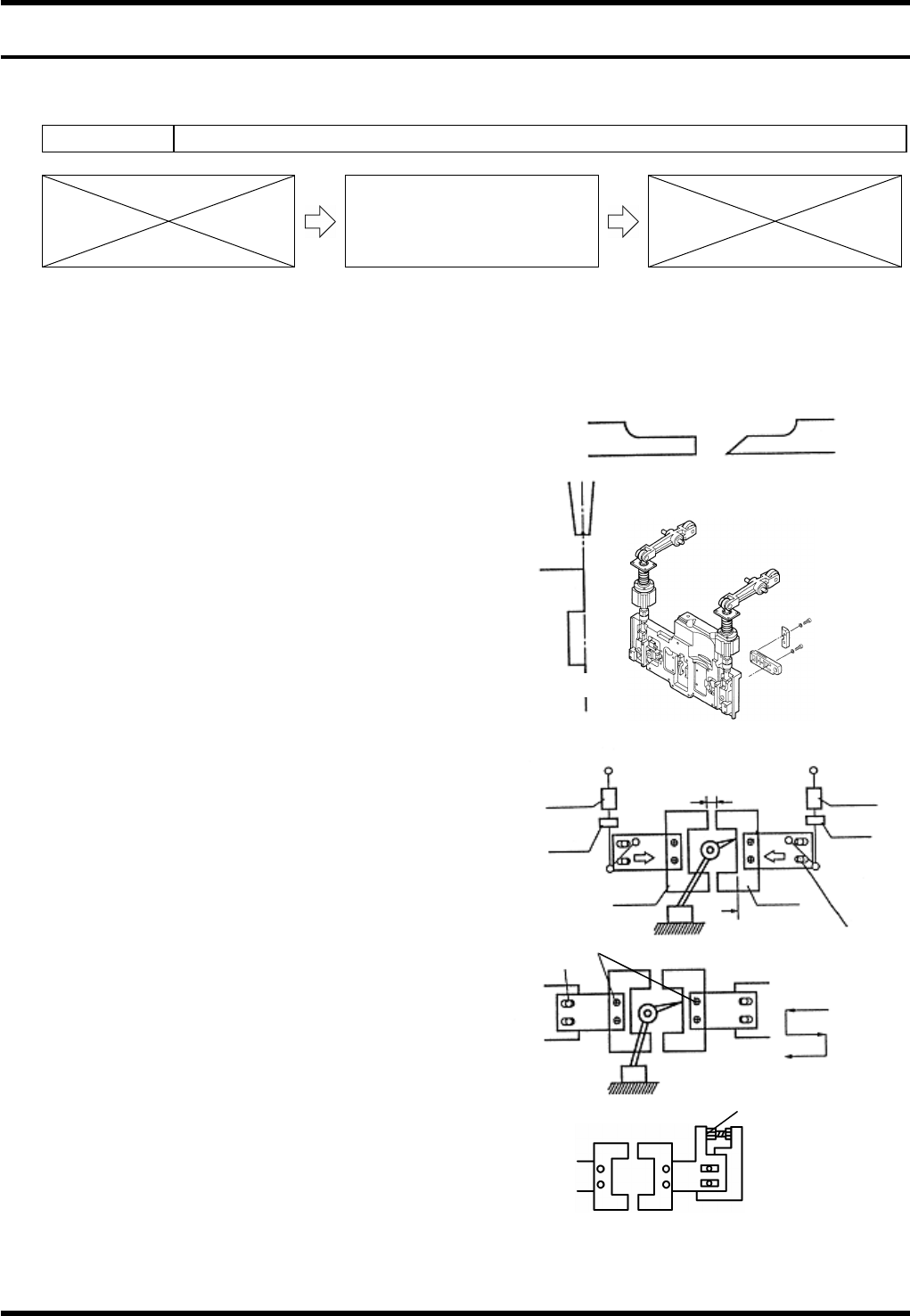
3. Loosen bolt (a) (4 pcs.).
4. Remove the cutters. (Blades A and B)
5. Loosen the bolts (b) and (c) fastening the slider.
6. Move the sliders to both sides.
7. Attach blade A.
8. Rotate the handwheel to set the cycle timer to
around 324°. (The blade A moves forward while
the handwheel is being rotated.)
9. Adjust the slider so that the blade A is in line with
the T- axis chuck (closed).
Refer to figure (a).
10. Tighten the bolt (b) to fix the slider.
11. Rotate the handwheel to move the cycle timer
back and forth between 295 - 340° and check
again.
12. Reattach the blade B and rotate handwheel to
set the cycle timer to 324°.
13. Shift the slider to allow the blade B to touch the
blade A, then tighten the bolt (c) temporarily.
14. Remove the blade A.
15. Set the dial gauge to the surface A and zero the
dial gauge.
Chuck
Cutter blade
Z axis side
Front side
AB
Drive-in amount
0.1 - 0.3 mm
Air damper
cylinder
Nut B
Bolt (c)
Blade B
Surface A
Blade A
Nut A
A
ir damper
cylinder
Bolt (a)
Bolt (b)
CT: 324°
CT: 324°
CT: 235°
Cutter
Slider
Adjustment bolt
Fig. (a)
AV131
MAINTENANCE MANUAL
8.4 Cutter Unit
D79MEC-W5-200-A0
8.4-2
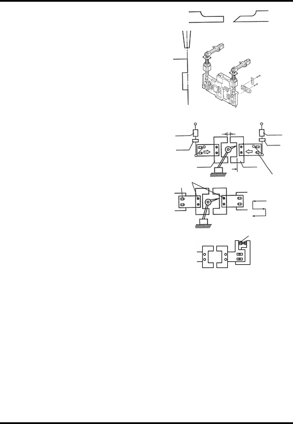
16. Rotate the adjust bolt to move the slider 0.1 mm
to the left and tighten the bolt (c) to secure the
blade A.
(Measure the movement of the slider while
observing the dial gauge.)
17. Dispose of component taping wastes inside the
dust box and remove the dial gauge.
18. Perform an insertion test to check component
taping wastes inside dust box.
=HINT=
Check the component taping to judge the
drawn length. Ensure a clean cut of
component taping is achieved.
19. If component taping cutting condition is not
satisfactory, gradually adjust blade B by 0.05 to
0.1 mm to the left.
(Repeat steps 14 to 18.)
=REMARKS=
Be sure to turn the power OFF when
replacing the cutter.
=CHECK=
Check that the air pressure setting on the
regulator for air damper cylinder is in the
range of 0.3 to 0.35 MPa.
Chuck
Cutter blade
Z axis side
Front side
AB
Drive-in amount
0.1 - 0.3 mm
Air damper
cylinder
Nut B
Bolt (c)
Blade B
Surface A
Blade A
Nut A
A
ir damper
cylinder
Bolt (a)
Bolt (b)
CT: 324°
CT: 324°
CT: 235°
Cutter
Slider
Adjustment bolt
AV131
MAINTENANCE MANUAL
8.4 Cutter Unit
D79MEC-W5-200-A0
8.4-3
8.4.2 Duct Cleaning and Height Adjustment
Unit No. N610060949AA
8.4.2 Duct Cleaning and Height
Adjustment
Duct Cleaning and Height Adjustment
17.
1. Turn the power ON and return to origin.
=REMARKS=
Make sure that the positioner rail is not
under the insertion unit.
2. Turn the <SERVO> switch OFF.
3. Call up the “IO control” screen from the
[Machine adjustment] menu screen and press
[Slider forward].
4. Turn the <HEAD BRAKE> switch OFF
(RELEASE).
5. Rotate the handwheel to set the cycle timer to
90°.
6. Turn the <HEAD BRAKE> switch ON (LOCK).
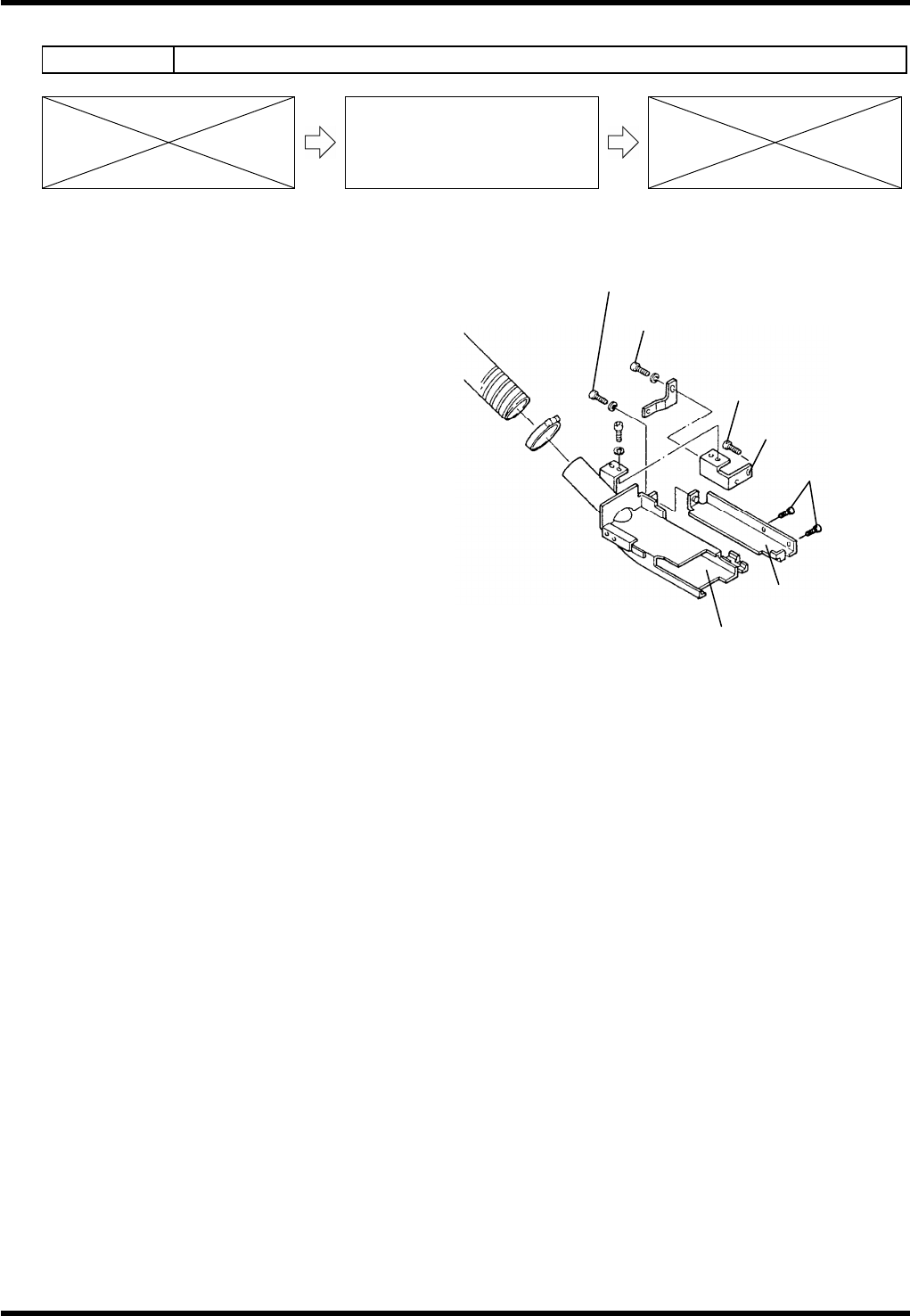
7. Loosen bolts (b) and (c).
8. Remove the duct and clean it.
9. Reattach the duct.
10. Check the height from the bottom of the duct to the PCB (1.6 mm thick).
=SPECIFICATION=
Height: 6.5 - 7.0 mm
11. Move the slide chuck back and forth to check that it does not interfere with the duct.
12. If not within the specification, loosen bolts (d) and (e) until the duct can move up/down.
13. Adjust the height from the bottom of the duct to the PCB (1.6 mm thick).
14. Tighten the bolts (d) and (e).
15. Check the duct height again.
16. Move the slide chuck back and forth to check that it does not interfere with the duct again.
Bracket (a)
Bolt (d)
Bolt (e)
Bracket (b)
Duct
Bolt (c)
Bolt (b)