Maintenance Manual.pdf - 第189页
AV131 MAINTENANCE MANUAL 8.4 Cut ter Unit D79MEC-W 5-200- A0 8.4- 4
AV131
MAINTENANCE MANUAL
8.4 Cutter Unit
D79MEC-W5-200-A0
8.4-3
8.4.2 Duct Cleaning and Height Adjustment
Unit No. N610060949AA
8.4.2 Duct Cleaning and Height
Adjustment
Duct Cleaning and Height Adjustment
17.
1. Turn the power ON and return to origin.
=REMARKS=
Make sure that the positioner rail is not
under the insertion unit.
2. Turn the <SERVO> switch OFF.
3. Call up the “IO control” screen from the
[Machine adjustment] menu screen and press
[Slider forward].
4. Turn the <HEAD BRAKE> switch OFF
(RELEASE).
5. Rotate the handwheel to set the cycle timer to
90°.
6. Turn the <HEAD BRAKE> switch ON (LOCK).
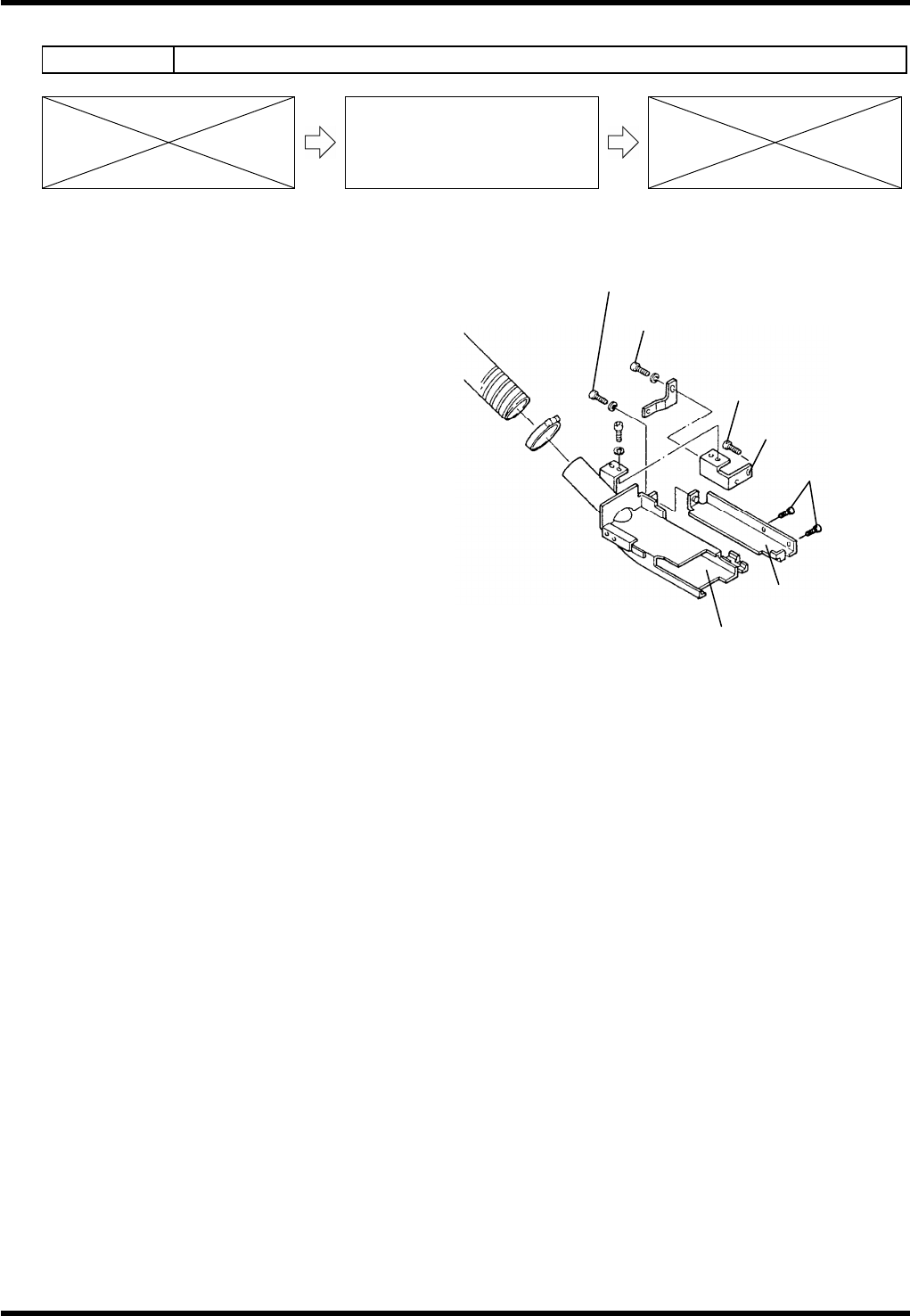
7. Loosen bolts (b) and (c).
8. Remove the duct and clean it.
9. Reattach the duct.
10. Check the height from the bottom of the duct to the PCB (1.6 mm thick).
=SPECIFICATION=
Height: 6.5 - 7.0 mm
11. Move the slide chuck back and forth to check that it does not interfere with the duct.
12. If not within the specification, loosen bolts (d) and (e) until the duct can move up/down.
13. Adjust the height from the bottom of the duct to the PCB (1.6 mm thick).
14. Tighten the bolts (d) and (e).
15. Check the duct height again.
16. Move the slide chuck back and forth to check that it does not interfere with the duct again.
Bracket (a)
Bolt (d)
Bolt (e)
Bracket (b)
Duct
Bolt (c)
Bolt (b)

AV131
MAINTENANCE MANUAL
8.4 Cutter Unit
D79MEC-W5-200-A0
8.4-4
AV131
MAINTENANCE MANUAL
8.5 Recognition and Lighting Unit
D79MEC-W0-400-A0
8.5-1
8.5. Recognition and Lighting Unit
D79MEC-W0-400-A0
8.5.1 Cleaning the Camera / Floodlight
Unit No. N610052084AA
8.5.1 Cleaning the Camera /
Floodlight
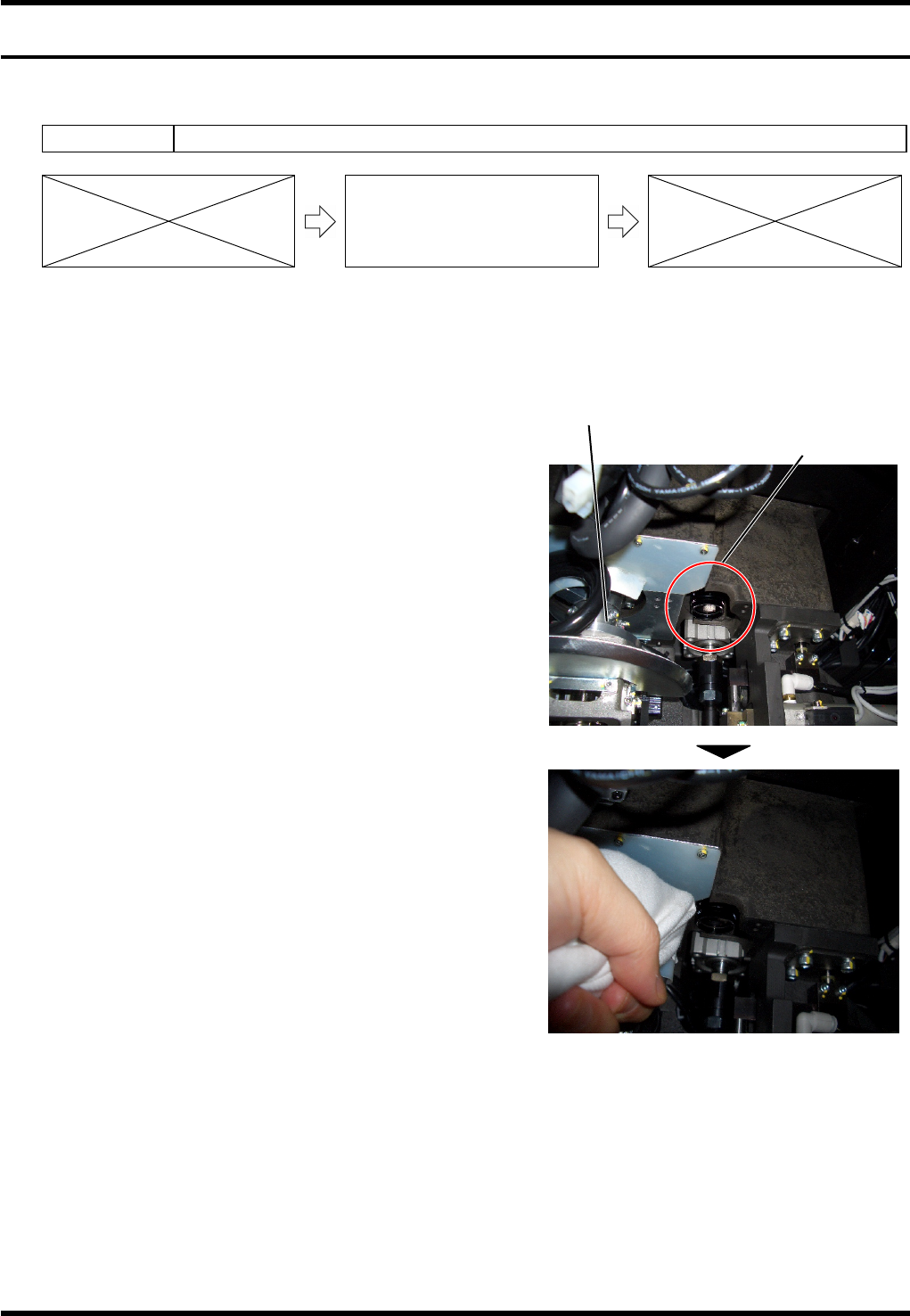
When ‘HOLE RECOG HOLE NOT IN SEARCH AREA’ occurs during the PCB hole recognition, it is likely
that the lens of the recognition camera is dirty. Procedure for cleaning the lens is shown below.
Procedure for Cleaning the Camera
18.
1. Prepare tools for cleaning.
Dry, soft cloth
2. Return the machine to the origin, and then turn the
<SERVO> switch or power supply OFF.
3. Open the machine front cover.
4. Remove the front inside cover.
5. The recognition camera is located at the right of the
motor for insertion head rotation. As shown in the right
photo, access the camera from beneath and wipe the
lens with the soft cloth prepared in step 1.
6. Execute the PCB hole recognition again to check that
“HOLE RECOG HOLE NOT IN SEARCH AREA” does
not occur.
=REMARKS=
Be careful not to smear the lens with grease.
Recognition camera
Insertion head