Maintenance Manual.pdf - 第203页
AV131 MAINTENANCE MANUAL 9.1 M o v ement Check D79MEC- 71-010-A0 9.1- 8
AV131
MAINTENANCE MANUAL
9.1 Movement Check
D79MEC-71-010-A0
9.1-7
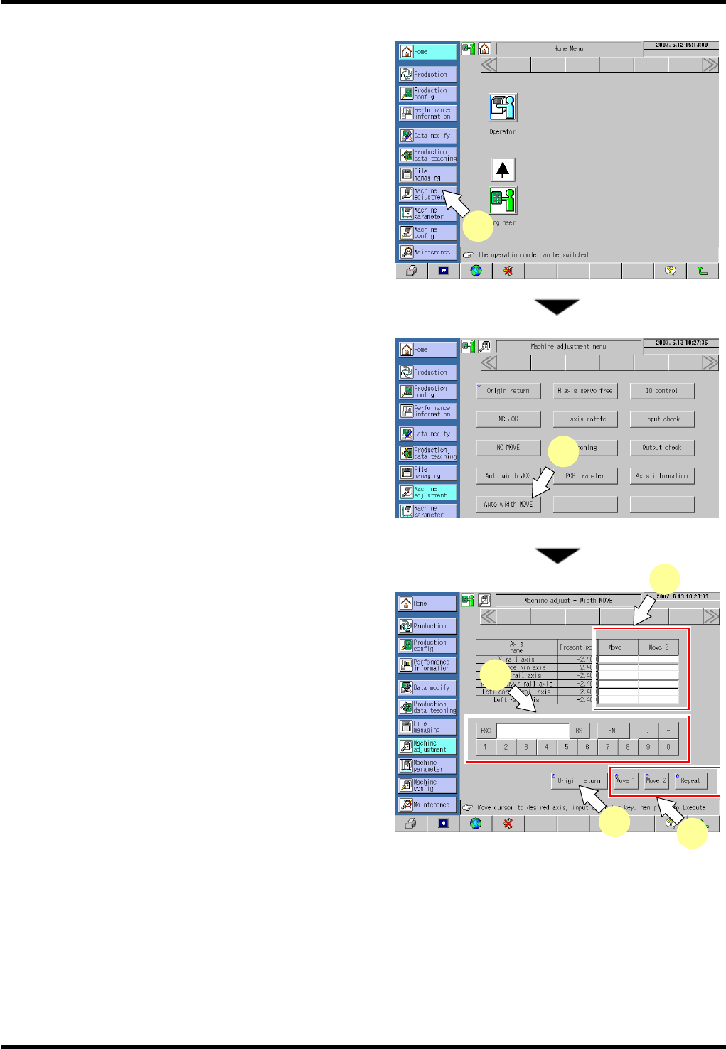
9.1.5 Width Adjust Axis Move Check
5.
1. Select [Machine Adjustment] from the main menu.
The “Machine adjustment menu” screen appears.
2. Press [Auto width MOVE].
The “Machine adjust - Width MOVE” screen
appears.
3. Press [Move 1] or [Move 2] field for the axis to be
moved.
4. Input a coordinate of the target position to move the
selected axis to.
5. Pressing <ENABLING> + [Move 1], [Move 2] and
[Repeat] moves the NC axis to the designated
coordinate.
=HINT=
Input the coordinates in [Move 1] and [Move 2]
respectively, and press [Repeat] to repeat the
movement to the designated coordinates of
MOVE 1 and MOVE2.
6. Press <ENABLING> + [Origin return] after completing movement check.
1
2
3
4
6
5

AV131
MAINTENANCE MANUAL
9.1 Movement Check
D79MEC-71-010-A0
9.1-8
AV131
MAINTENANCE MANUAL
9.2 Monitoring
D79MEC-71-020-A0
9.2-1
9.2. Monitoring
D79MEC-71-020-A0
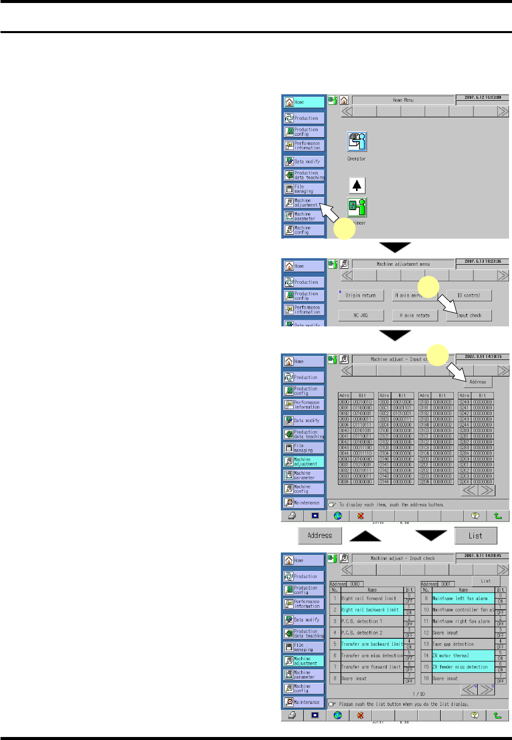
9.2.1 Monitoring
This function allows the status of the input signals (sensors, etc.) and output signals (solenoid valves, etc.) to
be monitored.
Procedure
26.
1. Press [Machine adjustment] from the main menu.
The “Machine adjustment menu” screen appears.
2. Press [Input check].
The “Machine adjust - Input check” screen
appears.
3. Press [Address].
The address screen listing the input signal names
by address is displayed.
=HINT=
The list screen and address screen can be
switched alternately.
4. Check if the statuses of the input signals listed
below the address are normal (ON/OFF).
If the input status of the sensor is not proper, the
sensor may be broken or disconnected. In such
case, the sensor needs to be replaced. Contact
us for details.
2
1
3