Semi Auto Machine Preparation.pdf - 第21页
semi automatic 0$&+,1( 35(3$5$7,21 35(,167$ //$7,21& +(&.6 Chapter Issue 1 Oct 02 Instal lation Ma nual 5.21 PRE-INST ALLA TION CHECKS Having remove d the transit bracket s and lo cated the machin e in pos…
semi automatic
0$&+,1(35(3$5$7,21
0$&+,1($66(0%/<
5.20 Installation Manual Chapter Issue 1 Oct 02
NOTE
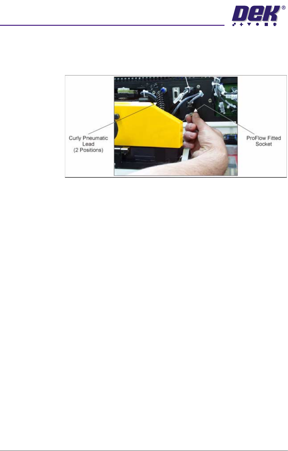
If the squeegee paste dispenser option is fitted to the print carriage, before
using ProFlow, ensure that the paste dispenser regulator gauge reads ’0’
pressure.

semi automatic
0$&+,1(35(3$5$7,21
35(,167$//$7,21&+(&.6
Chapter Issue 1 Oct 02 Installation Manual 5.21
PRE-INSTALLATION CHECKS
Having removed the transit brackets and located the machine in position,
prepare to install the machine, as follows:
1. Ensure machine mains isolator is OFF.
2. Connect the pneumatic supply to the connection on the external services
panel, as detailed in the Services Required chapter of this manual.
NOTE
Do not connect the electrical supply to the machine until the electrical
services have been verified, as stated in the Electrical Services section of
the Power Up Sequence chapter of this manual.
3. Check that all circuit breakers are in the ON position.
4. Ensure that all access covers and removable panels are closed and are in
place, Safety Features chapter refers.
5. Ensure that the E Stop buttons are in the fully out position. To check this,
push the E Stop button until it latches. Twist the button clockwise to release
it.
6. Check that all the cables for the monitor and keyboard/mouse are con-
nected.
semi automatic
0$&+,1(35(3$5$7,21
0$&+,1(/(9(//,1*
5.22 Installation Manual Chapter Issue 1 Oct 02
MACHINE LEVELLING
General Before operation, the machine height and level must be set.
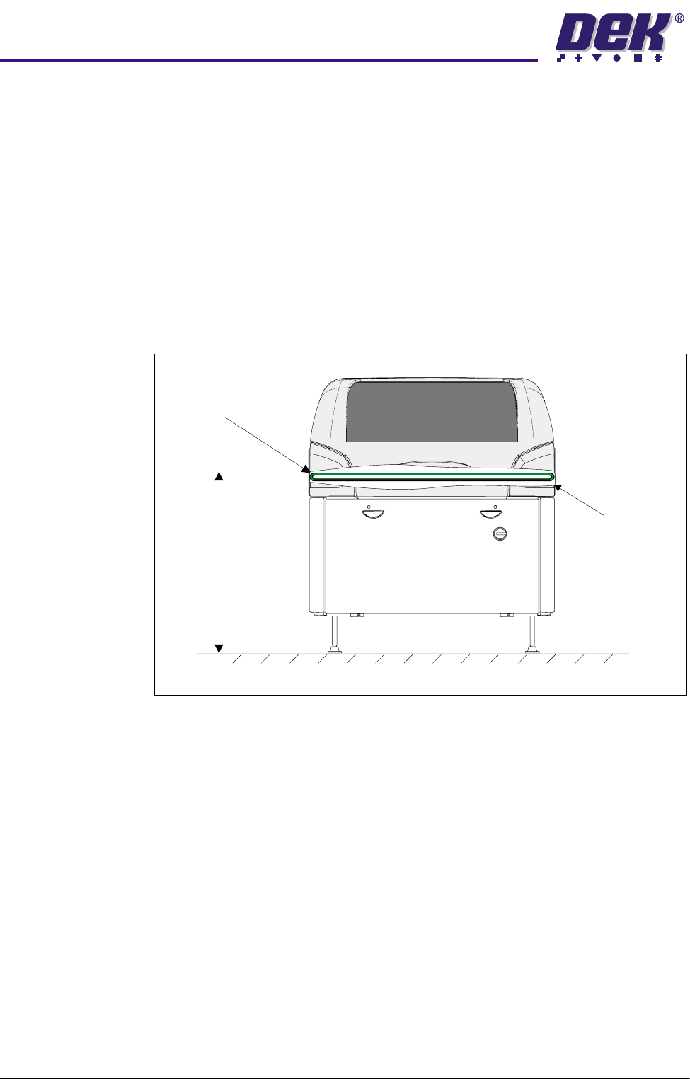
Machine Height The height of the machine is adjustable from 820mm to 980mm which is
measured from the floor to the top of the transport belts, Machine Height figure
below refers. Ideally the machine should be set at its lowest position, with the
machine legs screwed in.
NOTE
To achieve reliable DEK SPC testing and Cp/Cpk results, the securing arrange-
ment of the four machine legs must be correct in accordance with the Mounting
Feet Arrangement diagram, (Major Relocation chapter - Unpacking section).
This arrangement increases the rigidity of securing the feet to the frame.
Figure 5-10 Machine Height
Height to Top of
Transport Belts
820mm to 980mm
View on Front of Machine
Transport Belts
Cutaway to
Show Belt