Semi Auto Machine Preparation.pdf - 第4页
semi automatic 0$&+,1( 35(3$5$7,21 5(029$/35 2&('85(6 5.4 Instal lation Ma nual Chapter Issue 1 Oct 02 REMOV AL PROCEDURES T o remove the tr ansit bracket s from the mac hine, refer to t he following pr oc…
semi automatic
0$&+,1(35(3$5$7,21
75$16,7%5$&.(76
Chapter Issue 1 Oct 02 Installation Manual 5.3
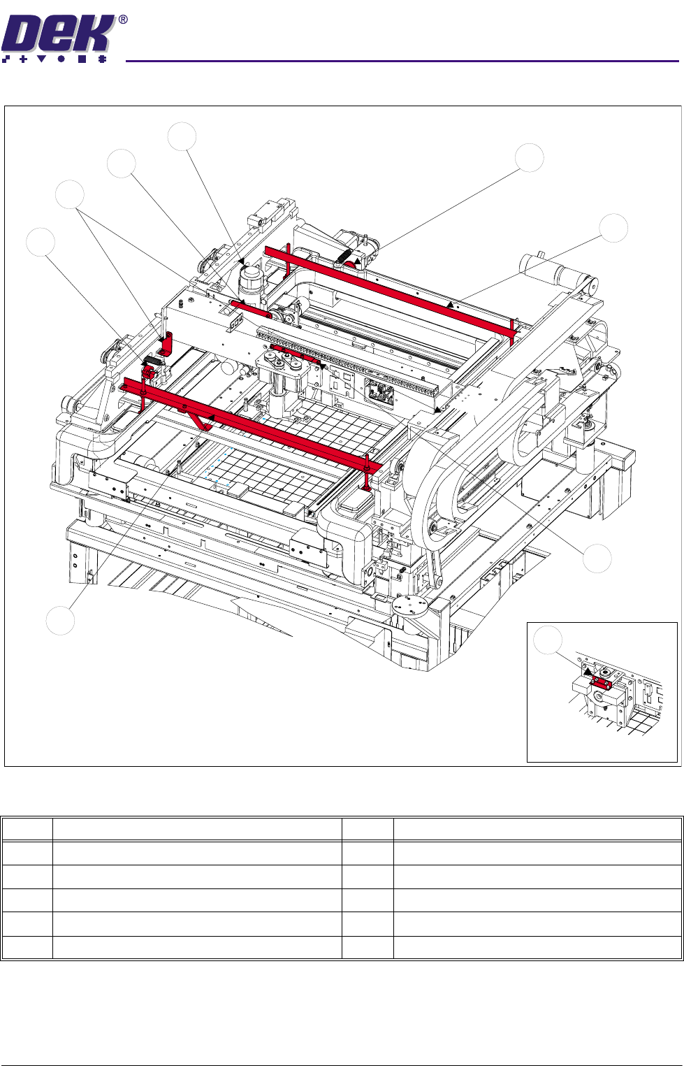
Figure 5-1 Transit Bracket Location
Item Description Item Description
1 Y Actuator Clamp 6 Print Carriage Stop (Left & Right)
2 Rear Transit Bracket 7 Paste Dispense Transit Bracket
3 Squeegee Transit Bracket 8 Rear X Actuator Clamp
4 Front Transit Bracket 9 ProFlow Transit Bracket
5 Forward X Actuator Clamp
1
5
6
7
8
4
2
3
ProFlow Option
9
semi automatic
0$&+,1(35(3$5$7,21
5(029$/352&('85(6
5.4 Installation Manual Chapter Issue 1 Oct 02
REMOVAL PROCEDURES
To remove the transit brackets from the machine, refer to the following proce-
dures:
Front Transit Bracket
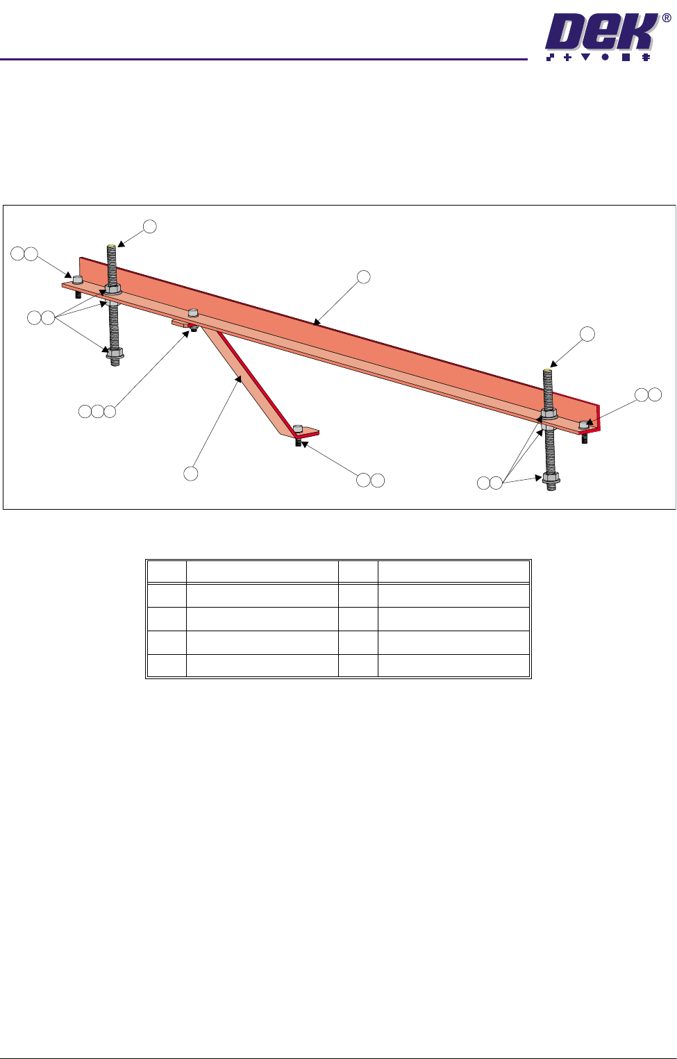
Figure 5-2 Front Transit Bracket (With Camera Bracket Fitted)
1. Remove the M5 cap head screw (Item 3) and washer (Item 8) securing the
camera transit bracket (Item 6) to the camera carriage. Loosen the M5 cap
head screw and nut at the top of the camera transit bracket and rotate the
bracket clear of the camera X axis timing belt.
2. On each of the M8 studs (Item 2), loosen the nuts and washers (Items 5 and
4) either side of the transit bracket, loosen the M8 nuts (Item 5) securing the
M8 studs (Item 2) to the screen chase. Unscrew the studs (Item 2) from the
screen chase.
3. Unscrew the two M5 cap head screws (Item 3) securing the front transit
bracket to the printhead.
4. Remove the front transit bracket.
Item Description Item Description
1 Front Transit Bracket 5 M8 Nut
2 M8 Stud 6 Camera Transit Bracket
3 M5 Cap Head Screw 7 M5 Ni-Loc Nut
4 M8 Washer 8 M5 Washer
3
1
6
2
2
8
8
3
7
8
3
3
8
4
5
4
5
semi automatic
0$&+,1(35(3$5$7,21
5(029$/352&('85(6
Chapter Issue 1 Oct 02 Installation Manual 5.5
Rear Transit Bracket
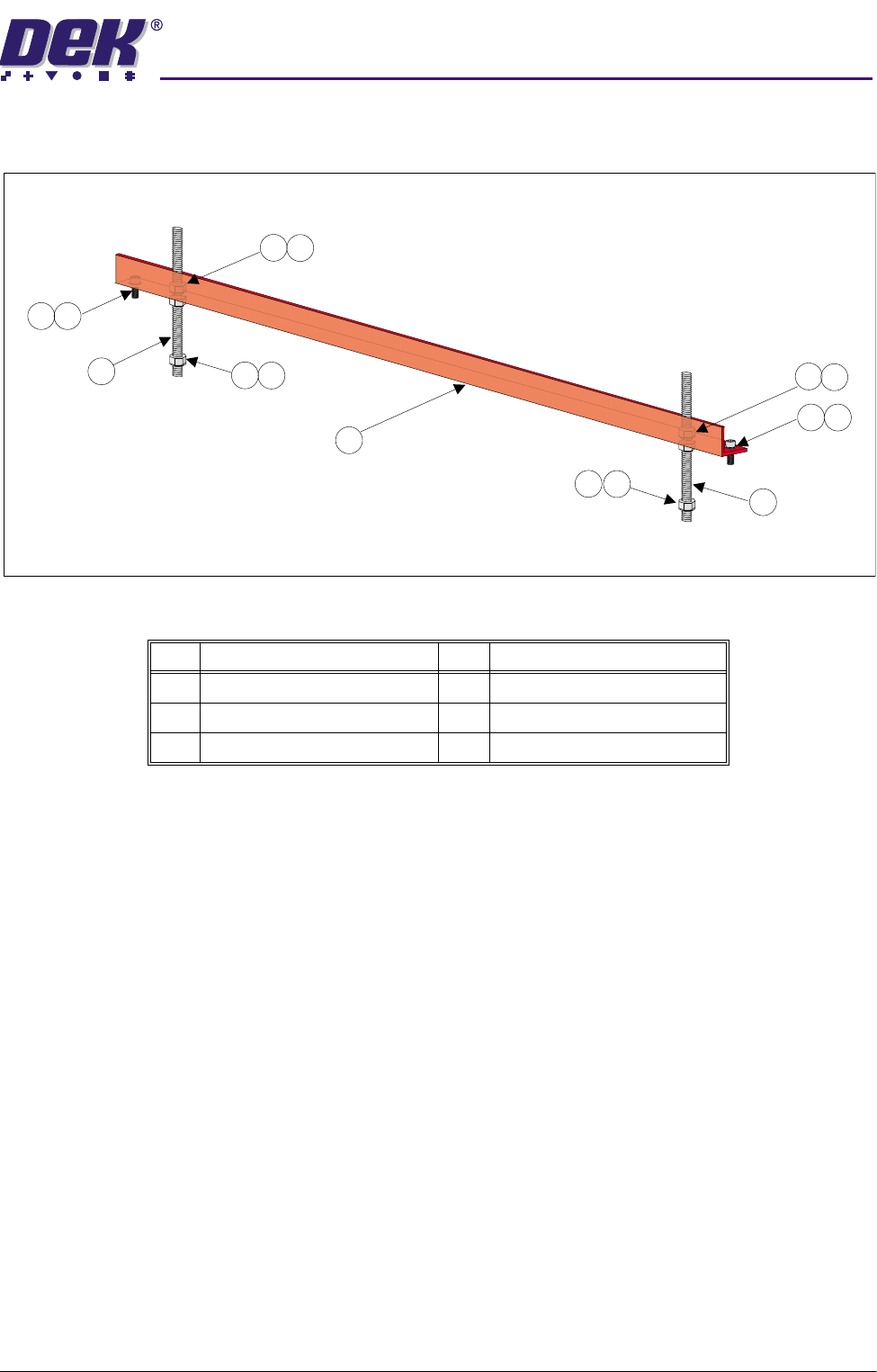
Figure 5-3 Rear Transit Bracket
1. Loosen the M8 nuts (Item 3) above and below the left and right hand sides
of the bracket (Item 6).
2. Unscrew the left hand and right hand M8 studs (Item 5) from the screen
chase.
3. Remove the two M5 cap head screws (Item 1) securing the left hand and
right hand sides of the bracket (Item 6) to the printhead casting.
4. Carefully remove the rear transit bracket.
Item Description Item Description
1 M5 Cap Head Screw 4 M8 Washer
2 M5 Washer 5 M8 Stud
3 M8 Nut 6 Rear Transit Bracket
1
2
1
2
3
3
4
3
4
3
4
4
5
5
6