X-Serie S_705 - 第21页
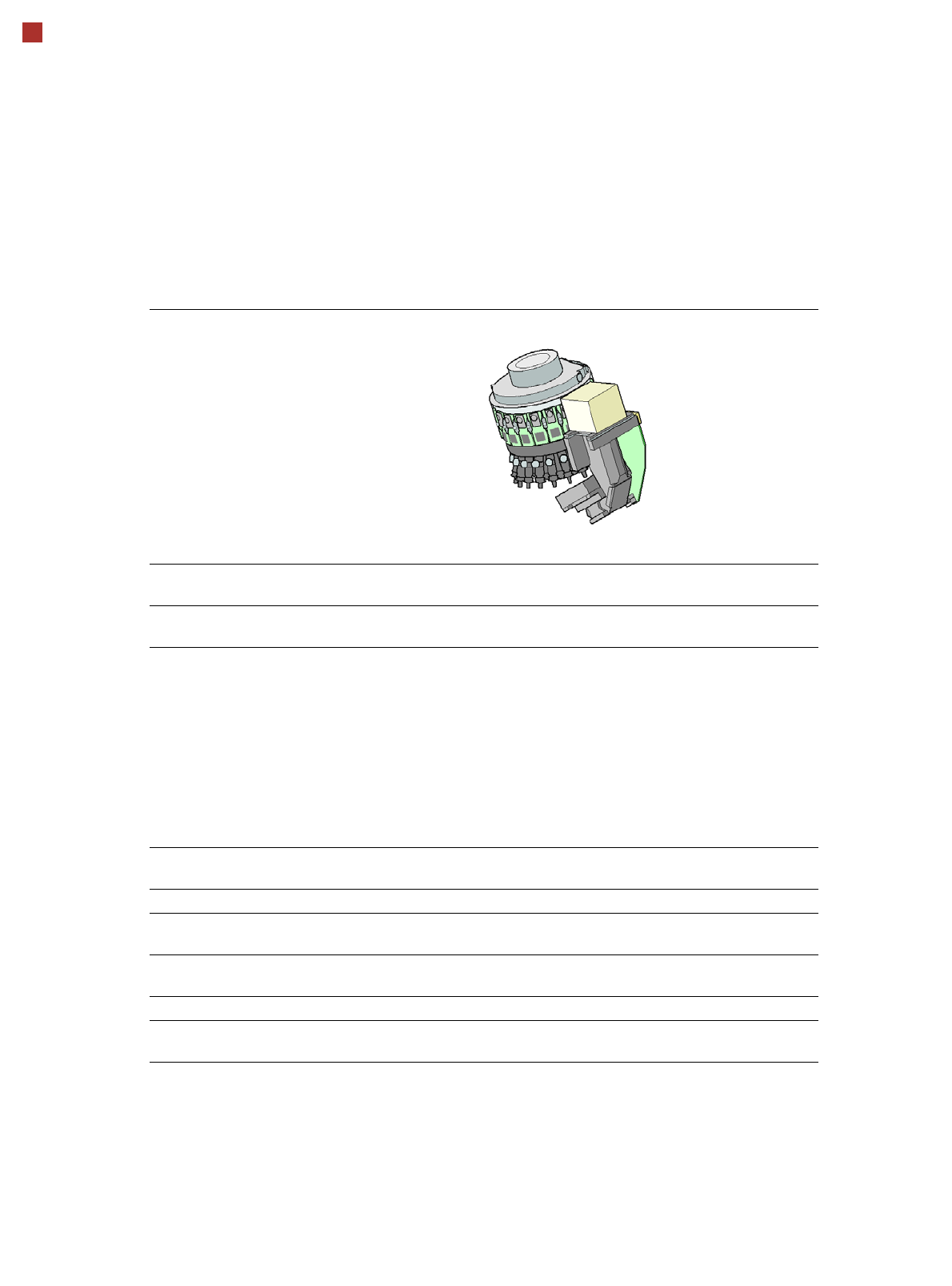
21 Placement heads SIPLACE MultiStar (CPP) SIPLACE MultiStar (CPP) With component camera type 30 With component camera type 33 (stationary camera) Component range a a) Please note that the placeable component range is al…
20
Placement heads
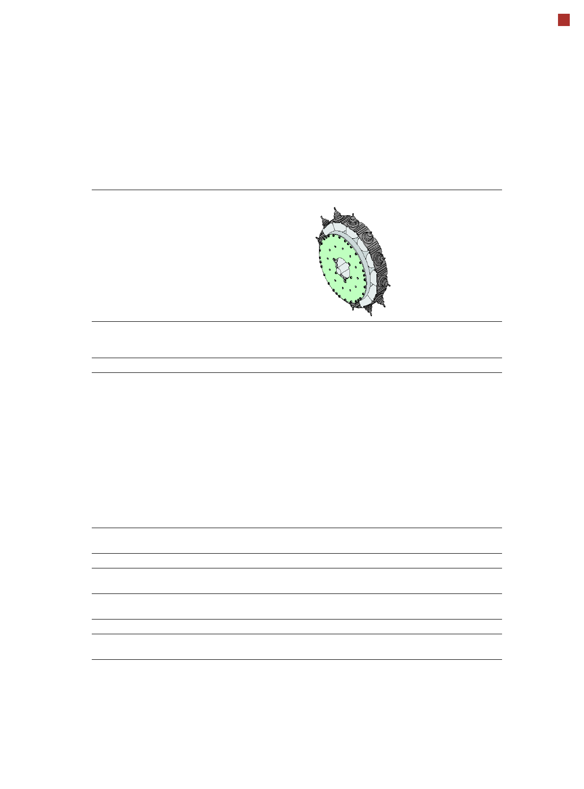
SIPLACE SpeedStar (C&P20 P)
SIPLACE SpeedStar (C&P20 P)
With component camera
type 23
With component camera type
41
Component range
a
a) Please note that the placeable component range is also affected by the pad geometry, the customer-spe-
cific standards, the component packaging tolerances and the component tolerances.
01005 to 2220, Melf, SOT,
SOD
03015 mmto 2220, Melf, SOT,
SOD, Bare-Die, Flip-Chip
Component spec.
Max. height
Min. lead pitch
Min. lead width
Min. ball pitch
Min. ball diameter
Min. dimensions
Max. dimensions
Max. weight
4 mm
0.25 mm
0.1 mm
0.4 mm
0.2 mm
0.4 mm x 0.2 mm
6 mm x 6 mm
1 g
4 mm
0.08 mm
0.03 mm
0.10 mm
0.05 mm
0.12 mm x 0.12 mm
6 mm x 6 mm
1 g
Programmable set-down
force
1.3 - 4.5 N 1.3 - 4.5 N
Nozzle types 40xx 40xx
X/Y accuracy
b
b) The SIPLACE benchmark value is measured during the machine acceptance tests. It corresponds to the
conditions set out in the SIPLACE scope of service and supply.
± 36 µm/3
± 48 µm/4
± 36 µm/3
± 48 µm/4
Angular accuracy ± 0.5° / 3
± 0.7° / 4
± 0.5° / 3
± 0.7° / 4
Illumination level 5 5
Possible illumination
level settings
256
5
256
5
21
Placement heads
SIPLACE MultiStar (CPP)
SIPLACE MultiStar (CPP)
With component camera type 30 With component camera
type 33
(stationary camera)
Component range
a
a) Please note that the placeable component range is also affected by the pad geometry, the customer-spe-
cific standards, the component packaging tolerances and the component tolerances.
01005 mm to 27 mm x 27 mm 0402 to 50 mm x 40 mm
b
b) A diagonal of 69 mm is possible during multiple measurements (e.g. 60 mm x 10 mm).
Component spec.
Max height
c
Max. height
d
Min. lead pitch
Min. lead width
Min. ball pitch
Min. ball diameter
Min. dimensions
Max. dimensions
Max. weight
c) CPP head: in low installation position (stationary component camera not possible).
d) CPP head: in high installation position
6.0 mm
8.5 mm
0.3 mm
0.15 mm
0.25 mm
e
0.35 mm
f
0.14 mm
e
0.20 mm
f
0.4 mm x 0.2 mm
27 mm x 27 mm
4 g
e) For components < 18 mm x 18 mm
f) For components ≥ 18 mm x18 mm
11.5 mm
0.3 mm
0.15 mm
0.35 mm
0.2 mm
1.0 mm x 0.5 mm
50 mm x 40 mm
8 g
Programmable set-down
force
1.0 - 10 N 1.0 - 10 N
Nozzle types 20xx, 28xx 20xx, 28xx
X/Y accuracy
g
g) The SIPLACE benchmark value is measured during the machine acceptance tests. It corresponds to the
conditions set out in the SIPLACE scope of service and supply.
± 41 µm/3
± 55 µm/4
± 34 µm/3
± 45 µm/4
Angular accuracy ± 0.4° / 3
h
, ± 0.5° / 3
i
± 0.5° / 4
h
, ± 0.7° / 4
i
h) Component dimensions between 6 mm x 6 mm and 27 mm x 27 mm.
i) Component dimensions smaller than 6 mm x 6 mm.
± 0.2° / 3
± 0.3° / 4
Illumination level 5 6
Possible illumination
level settings
256
5
256
6
22
Placement heads
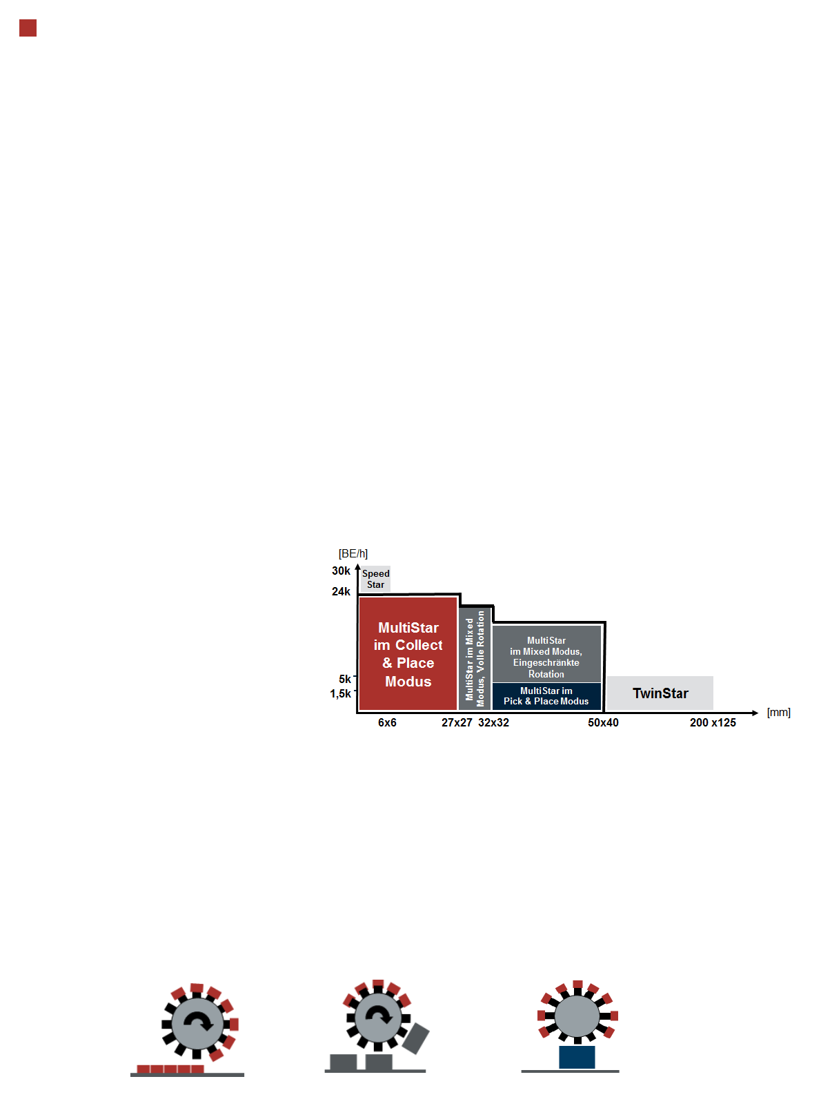
SIPLACE MultiStar (CPP)
Increased performance and flexibility
The SIPLACE Multistar is the
perfect SIPLACE solution:
• In an increasingly complex
production environment
• For an increasing diversity
of setup and production
strategies
• For a wide spectrum of
components
• For frequent product
changeovers.
It is even possible to place
larger components without a
noticeable drop in perfor-
mance. The SIPLACE Mul-
tistar is perfectly designed for
integration into a flexible and
speed-optimized production
environment.
One head for all applica-
tions
• The SIPLACE MultiStar
offers top flexibility
• It combines
Collect&Place mode with
Pick&Place mode
One head supports three
placement modes:
Elimination of bottlenecks
• A wider component spec-
trum
• Optimum performance uti-
lization
• More feeder module
tracks for the TwinStar
• Improved throughput due
to perfect line utilization
• More products in one set-
up family
Throughput
• Up to 23,500 components/
h benchmark value
• Up to 19,000 components/
h IPC 9850 performance
Collect&Place mode
Pick&Place mode
Mixed mode