X-Serie S_705 - 第43页
43 Component feeding SIPLACE JTF-S/JTF-M Technical data SIPLACE JTF-S SIPLACE JTF-M Width 162 mm 177 mm Height 587 mm 587 mm JEDEC waffle pack tray spec- ification JEDEC Standard: 95-1 & IEC 60286-5 Storage capa city…
42
Component feeding
SIPLACE JTF-S/JTF-M
The SIPLACE JTF-S/JTF-M
is an automatic and fast
changer for standard JEDEC
waffle pack trays. On
SIPLACE X-Series S
machines, a SIPLACE JTF-
S/JTF-M can be installed on
a fixed table instead of a
component trolley. The
SIPLACE JTF-S/JTF-M
occupies a fixed area of
tracks on the fixed table.
The SIPLACE JTF-S/JTF-M
is available in two versions
• SIPLACE JTF-S
• SIPLACE JTF-M
SIPLACE JTF-S
The SIPLACE JTF-S stores
a stack of up to 30 thin or 20
thick JEDEC waffle pack
trays and supplies them in
succession. The placement
machine can be supplied
with one component type at
constant waffle pack tray
changeover time.
SIPLACE JTF-M
Depending on the magazine
type, the SIPLACE JTF-M
stores up to 18 thin or 14
thick JEDEC waffle pack
trays in an exchangeable
cassette and supplies them
as required. The placement
machine can therefore be
supplied with different
component types at variable
waffle pack tray changeover
times.
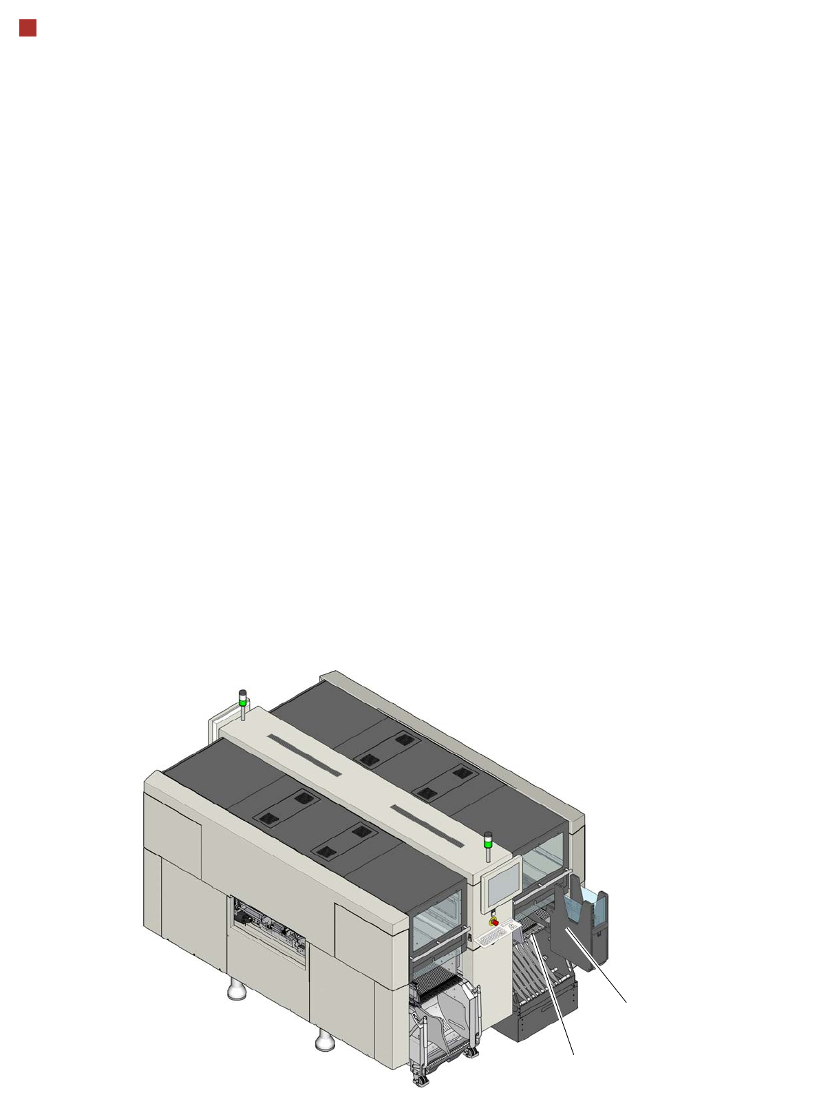
JTF-S/JTF-M
Fixed component table

43
Component feeding
SIPLACE JTF-S/JTF-M
Technical data
SIPLACE JTF-S SIPLACE JTF-M
Width
162 mm 177 mm
Height
587 mm 587 mm
JEDEC waffle pack tray spec-
ification
JEDEC Standard: 95-1 & IEC 60286-5
Storage capacity
Waffle pack tray, thin 30 JEDEC waffle pack trays 18 JEDEC waffle pack trays
Waffle pack tray, thick 20 JEDEC waffle pack trays 14 JEDEC waffle pack trays
Waffle pack tray changeover
time
< 5 seconds (depending on
application)
--
Slot n to n+1 -- 3.5 seconds
Slot 1 to 18 -- 10 seconds
Slot 18 to 1 -- 8.9 seconds
Cassette
--
Dimensions -- approx. 330 mm x 150 mm x 230
mm
Max. load capacity -- 2.7 kg (150 g each for 18 slots)
Pneumatics
4.1 bar to 5.5 bar 5.2 bar to 9 bar
Compressed air consumption
< 28.3 NL/min. < 28.3 NL/min.

44
Digital SIPLACE Vision system
The digital Vision system
ensures fast and reliable
component recognition, cou-
pled with user-friendly han-
dling. The system identifies
each individual component
by its geometry and color.
Even complex component
shapes, such as flip chip or
CCGA are detected with high
reliability.
This component recognition
check is performed in a sin-
gle step, with no extra time
involved but with optimum
scanning of each individual
component.
This digital Vision system is
not only used in the compo-
nent cameras but also in the
PCB camera. In addition to
the precise recognition of
components, this also guar-
antees reliable detection of
ínkspots and PCB fiducials.
The benefits at a glance:
• Extremely fast and reliable
component recognition
• Shortest cycle times
• Robust measurement
based on the geometry
and color
• Straightforward program-
ming
• Offline programming of
component shapes
• Rapid introduction of new
products (NPI)
• Open architecture allows
you to quickly adapt to
new requirements
• Optimum placement
results based on individ-
ual measurement of each
component
The SIPLACE Vision sys-
tem offers inspection rou-
tines and functions to
enhance the quality of com-
ponent recognition.
The benefits at a glance:
• Maximum placement
quality
• High first pass yield
• Reduction of operating
costs
Examples of digital vision system analysis times
Evaluation times only play a role in the P&P process.
03015 9 ms
PLC44 17 ms
BGA 225 balls 18 ms
Digital vision cameras
SIPLACE SpeedStar camera, type 23
SIPLACE SpeedStar camera, type 41
SIPLACE MultiStar camera, type 30
SIPLACE TwinStar standard camera, type 33
SIPLACE TwinStar high resolution camera, type 25
SIPLACE PCB camera, type 34