QP-242E 工程师培训手册 (6.0).pdf.pdf - 第32页
FK-9F98-07 QP242E Training Text for Service Engineers 6th edition 4. Axis Zero Setting Adjustment [ 3 / 6 ] Fuji Machine Mfg. Co., Ltd. Okazaki SMT Equipment Quality Assurance Dept. Technical Support Div. Section No.2 4-…
FK-9F98-07 QP242E Training Text for Service Engineers
6th edition 4. Axis Zero Setting Adjustment [2/6]
Fuji Machine Mfg. Co., Ltd. Okazaki
SMT Equipment Quality Assurance Dept.
Technical Support Div. Section No.2
4-2
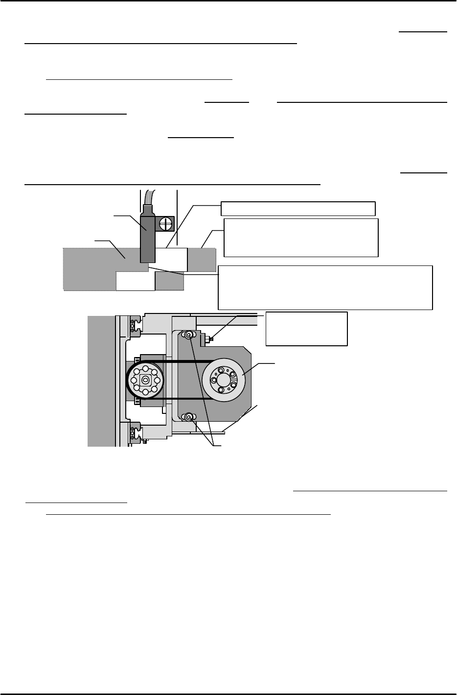
[4-5] X-Axis Zero Setting Adjustment and Belt Tension Adjustment (Same Procedure for all Module Types)
1) While watching the displayed counter value, turn the X-axis motor by hand to the 4000 pulse
position (-4000 pulse position at rear part-supply machines).
2) Move the head to the mechanical stopper at the machine's right side (as viewed from the part
supply side), then attach the timing belt and adjust its tension.
Belt tension tolerance:
:
227HZ±10HZ
After adjusting the belt tension, move the head back to right-side mechanical stopper position
and verify that the counter reading is within 40 00±200pulses (-4000 pulse position at rear
part-supply machines).
* Flip chip modules have a coupling drive system rather than a belt drive. At these modules,
adjust the X-axis to a 4000±100 pulse position .
3) After completing the above adjustment, adjust the X-axis deceleration sensor position so that
the sensor switches on at the -5500 pulse position. Following this adjustment, use the
"CHECK, X006, X AXIS ZERO" I/O to verify that the sensor switches on at the -5500±100
pulse position (5500 pulse position at rear part-supply machines).
[4-6] Y-axis Zero Setting Adjustment
1) Adjust in the same manner as for the X-axis (see above), so that the distance from the zero
setting completion position to the mechanical stopper is 4000 ± 100 pulses (-4000 at rear
part-supply machines), and so that the deceleration sensor switches on at the
-6000 ± 100 pulse position (6000 at rear part-supply machines).
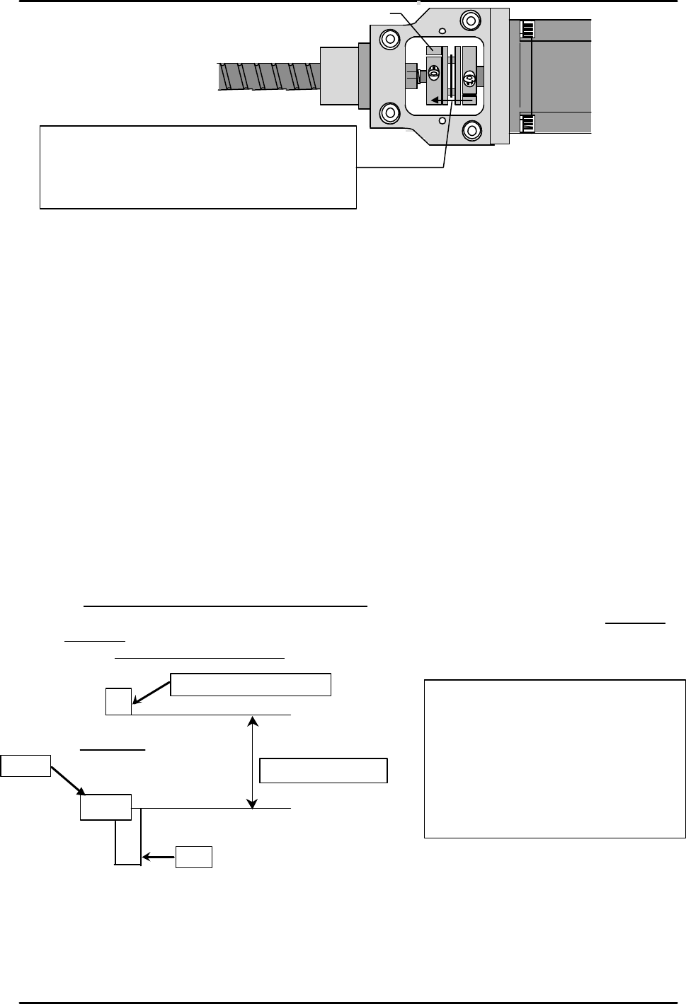
2) Verify that the coupling slides smoothly (is centered) between the ballscrew and the motor
shaft. Install the coupling so that its center is aligned with the center between axes (the
best way to do this is to secure the coupling with it pressed against the end of the ballscrew).
Be sure that there is no tensile or compressive stress acting on the coupling.
3) Use a torque wrench to tighten the coupling.
Y-axis coupling tightening torque: 34.0 kg.cm
Zero setting completion position
Deceleration sensor on position.
Move the head to the -5500 pulse position and
adjust the sensor position so that the sensor
switches on at that point.
Mechanical stopper position.
Move the motor to the 4000 pulse
position, then attach the belt.
X-axis deceleration sensor
dog
X axis HEAD
Mounting bolt
Motor pulley
Belt tension
adjusting bolt
FK-9F98-07 QP242E Training Text for Service Engineers
6th edition 4. Axis Zero Setting Adjustment [3/6]
Fuji Machine Mfg. Co., Ltd. Okazaki
SMT Equipment Quality Assurance Dept.
Technical Support Div. Section No.2
4-3
[4-7] Z-Axis Zero Setting Adjustment and Belt Tension Adjustment (for all Module Types)
It change the way of the adjustment for Z-axis Zero setting, because it occurs a problem that a
nozzle interferes with the lighting when Zero setting on the lighting unit for Camera type 7.
[New adjustment]
1) Remove the Single holder and the Index holder.
2) Zero setting for Z-axis. (Set “PLM* Zero Offset Z” in Proper Data to 0.)
3) Put the measured jig for Mark Camera resolution (AJPJ0062) on the conveyor, and clamp it.
4) Put the following jig for each holder type on the jig, AJPJ0062.
Index Holder Z9417BHPJ0040 (It is put a carved seal “I” on the body)
Single Holder (stroke=2mm) Z9417BHPJ0050 (It is put a carved seal “S-2” on the body)
Single Holder (stroke=3.5mm)Z9417BHPJ0060 (It is put a carved seal “S3.5” on the body)
5) Turn the servo OFF.
6) Lower Z-axis manually until the holder installing face of the head touches on top of the jig.
7) Adjust the dog so that the reduced sensor turns ON at this position. (The difference between
the position of touching to jig and the position of reduced sensor ON is +/-20 pulse.)
8) Calculate the counter from the position of reduced sensor to upper mechanical end by
moving the Z-axis.
9) Remove the timing belt, and set the counter of the motor to the value which minus 5000
pulse from calibrated value on (8).
10) Raise the Z-axis to the upward end to install the timing belt.
When installing the timing belt, adjust the belt tension at the same time.
Tolerance for belt tension : 434HZ +/- 10HZ
11) Down the Z-axis, and verify that the position of the reduce sensor ON is within –5000 +/-
170 pulse
12) Set the "PLM* Escape Position Z" in Proper data to "2000".
Secure the coupling so that its center is aligned with the
center between axes. (the best way to do this is to secure
the coupling with it pressed against the end of the
ballscrew). Be sure that there is no tensile or compressive
stress acting on the coupling.
Motor
Ballscrew
Y-axis coupling
The counter value for the mechanical
stopper upward end
Index Holder : about 5600 pulse
Single Holder : about 2500 pulse
Note:)
These values are just reference value.
There are difference modules by module.
Sensor
Dog
Pulse between this
Up side mechanical end
FK-9F98-07 QP242E Training Text for Service Engineers
6th edition 4. Axis Zero Setting Adjustment [4/6]
Fuji Machine Mfg. Co., Ltd. Okazaki
SMT Equipment Quality Assurance Dept.
Technical Support Div. Section No.2
4-4
[Old adjustment]
1) Adjust in the same manner as for the X-axis (see above), so that the distance from the zero
setting completion position to the mechanical stopper is 6000 ± 170 pulses, and so that the
deceleration sensor switches on at the – 5000 ± 100 pulse position.
Belt tension tolerance :
434HZ ± 10HZ
2) Set the "PLM Zero Offset Z" in Proper data to "2000".
3) Perform another zero setting and verify that the distance from the zero setting completion
position to the mechanical stopper is 4000 ± 170 pulses, and that the deceleration sensor
switches on at – 7000 ± 100 pulses.
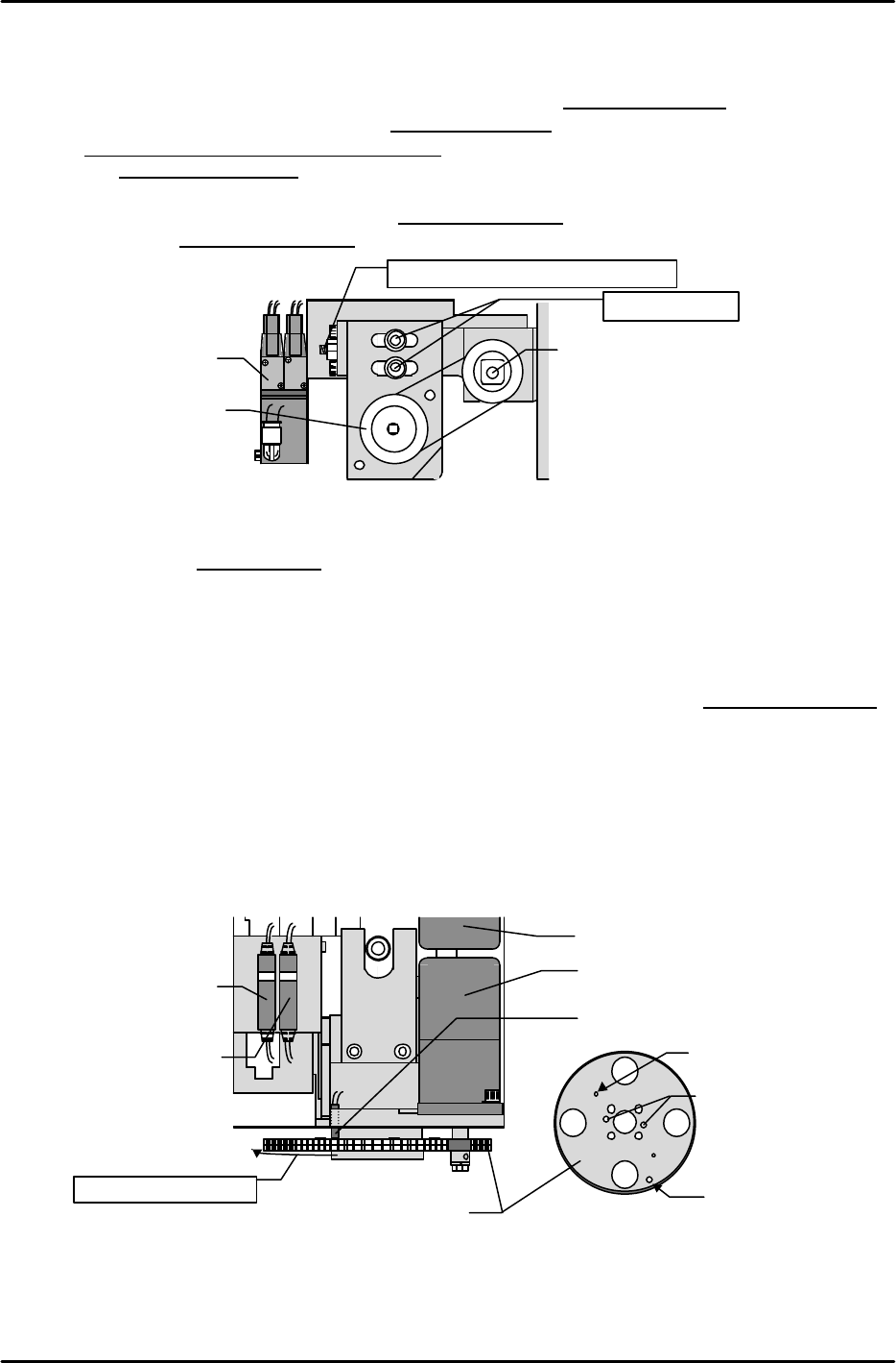
[4-8] Q-Axis Zero Setting Adjustment (Same Procedure for all Module Types)
1) Loosen the hollow bolt beside the Q-axis deceleration sensor and adjust the sensor height so
that there is a 0.2 to 0.3mm gap between the sensor and the gear. After making this
adjustment, slowly turn the gear 1 complete revolution to verify that the sensor activates only
at the dog hole position.
2) After the zero setting is completed, turn the gear back until the dog is past the sensor.
Slowly turn the gear in the zero setting direction, stopping at the point where the sensor
switches on (sensor LED changes from green to red). Use the [STROKE] è [NEXT AXIS]
commands to select the Q-axis. If the Q-axis counter reading is in the 4500 to 6000 pulse
range, the adjustment is complete.
* If the counter reading is not within this range, make an alignment mark on the gear (scissors
gear), then turn the motor back to the 4500 to 6000 pulse range and disengage the motor from
the gear. Re-engage the motor at the position where the sensor amplifier's red lamp goes off.
After re-engaging the motor, verify that the scissors gear engagement position is deviated by
the amount of one gear tooth (this is done by looking at the aligning holes from below the
gear).
Q axis motor
Q-axis deceleration sensor
Pressure sensor amplifier
Z-axis deceleration
sensor amplifier
Q scissors gear
Z axis motor
Q-deceleration dog
Holder Installing hole
Aligning holes
Zero setting direction
Belt tension adjusting bolt
Z-axis Ball screw
Z-axis motor pulley
Installing bolt
Solenoid valve