QP-242E 工程师培训手册 (6.0).pdf.pdf - 第45页
FK-9F98-07 QP242E Schooling Text for Service Engineer 6th edition 6. Proper Data Measurement [ 4 /20] Fuji Machine Mfg. Co., Ltd. Okazaki SMT Equipment Quality Assurance Dept. Technical Support Div. Section No.2 6- 4 [ 6…
FK-9F98-07 QP242E Schooling Text for Service Engineer
6th edition 6. Proper Data Measurement [3/20]
Fuji Machine Mfg. Co., Ltd. Okazaki
SMT Equipment Quality Assurance Dept.
Technical Support Div. Section No.2
6-3
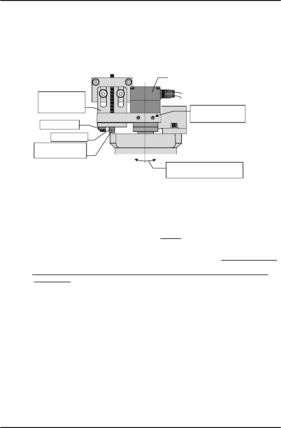
5) Loosen the bracket bolt, then turn the adjusting bolt to move the camera up and down until
the real image is in focus. When focused, retighten the bracket bolt.
6) Slightly loosen the adjusting bolt (do not loosen to the point where it makes contact with the
camera bracket) and insert an R-pin into the head’s through-hole to prevent falls.
[6-4] Securing the Half Mirror
1) After focusing the camera, partially cover the light source unit’s dispersion plate and check
the gap to the end of the half mirror.
2) Remove the light source unit again, and then, after noting the current half mirror position
(length), remove the half mirror from the lens.
3) Remove the half mirror set bolts (3 bolts) and apply silicone to them. Use care to avoid
dropping and losing the set bolts.
4) Based on the previously noted gap extending to the dispersion plate’s top face and the half
mirror position at that time, calculate the final position so that the gap is approximately 1mm,
then secure the half mirror at that position before the sealer dries.
Note: Avoid over-tightening the half mirror’s set bolts as this can adversely affect the lens
performance.
5) Mount the light source unit and verify that the gap is appropriate.
Hole where R-pin
is inserted
Focus by
moving bracket
up and down
Fulcrum pin
Set screw
Camera
Mount in a perpendicular
position (no tilt)
Verify that camera
lock bolt is tight
FK-9F98-07 QP242E Schooling Text for Service Engineer
6th edition 6. Proper Data Measurement [4/20]
Fuji Machine Mfg. Co., Ltd. Okazaki
SMT Equipment Quality Assurance Dept.
Technical Support Div. Section No.2
6-4
[6-5] Checking the X-axis Stroke
1) Remove the camera measurement plate jig and turn on the “Y022 CVR BD STPR IN” I/O at
the relevant module to raise the stopper. Clamp a maximum sized board with the board
against the stopper.
2) Move the head until the left edge of the maximum sized board is aligned with the mark
camera’s cross-hairs (vertical line), and check the servo counter value at this position. If the
counter value is 400 pulses (1mm) or more from the Min Limit or Max Limit, the board
stopper position (see above) and camera tilt adjustments are OK.
3) Check the right edge of the board in the same manner.
If the adjustment results are not OK, readjust the board stopper position and the camera tilt.
[6-6] Mark Camera X,Y,Q
1) Clamp a camera measurement plate jig, and, while watching the monitor, move the head until
the center of the plate jig’s mark is aligned with the camera center.
2) With the jig mark centered, use the following command sequence to perform an automatic
measurement: [RESOLUTION] à [MARK CAMERA] à [START].
3) Following the automatic measurement, check the measurement resolution. If it is within a
“1140326 (17.4um) to 1218969 (18.6um)” range for the Mark Camera X and Y, proceed to the
[Mark Camera Q] adjustment. If the measurement resolution is not within the above range,
the camera height (focus) is incorrect. In this case, readjust the camera height, then check the
Mark Camera X and Y values again.
[Ex] If the measured values are too low, raise the camera.
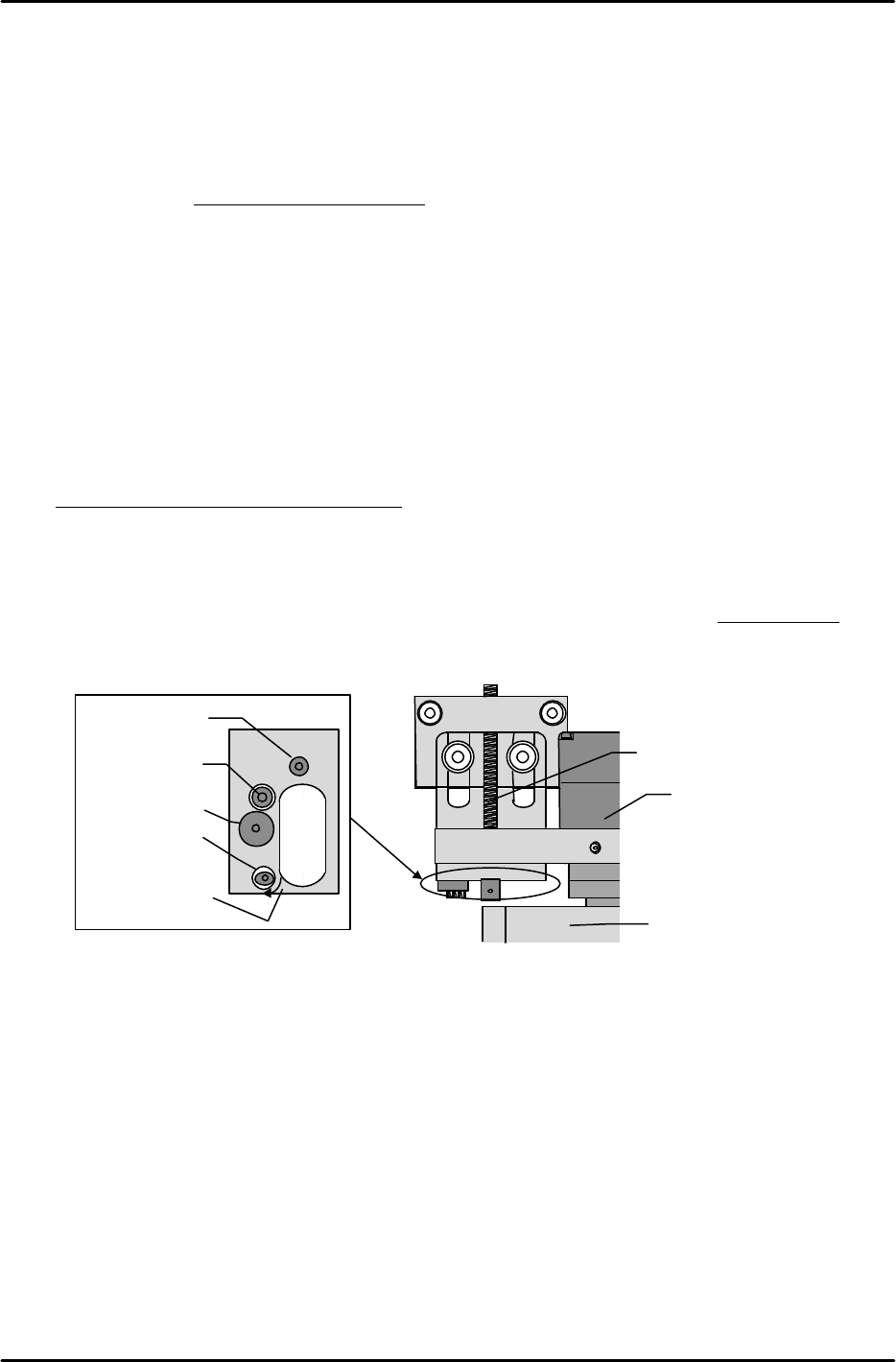
4) Loosen the lock bolt beside the camera and turn the eccentric bolt until the Q-value is “0”.
After re-tightening the lock bolt, check the measurement again.
Bottom View
Set screw
Fulcrum pin
Lock bolt
Eccentric pin
M/C rear
M/C front
+
Arrow indicates
“+” direction
Set screw
Camera
Light source unit
FK-9F98-07 QP242E Schooling Text for Service Engineer
6th edition 6. Proper Data Measurement [5/20]
Fuji Machine Mfg. Co., Ltd. Okazaki
SMT Equipment Quality Assurance Dept.
Technical Support Div. Section No.2
6-5
[6-7] Mark Read Pos. X,Y
1) Execute the following command sequence to turn on the camera lamp: [CAMERA] à
[CAMERA POS] à [MARK CAMERA].
2) While watching the image monitor, move the head so that the plate jig’s reference pin hole is
at the camera center.
3) With the reference pin hole centered, press the [SET] button to begin the automatic [Mark
Read Pos. X,Y] measurement. Leave the plate jig as it is when proceeding to the next
measurement item.
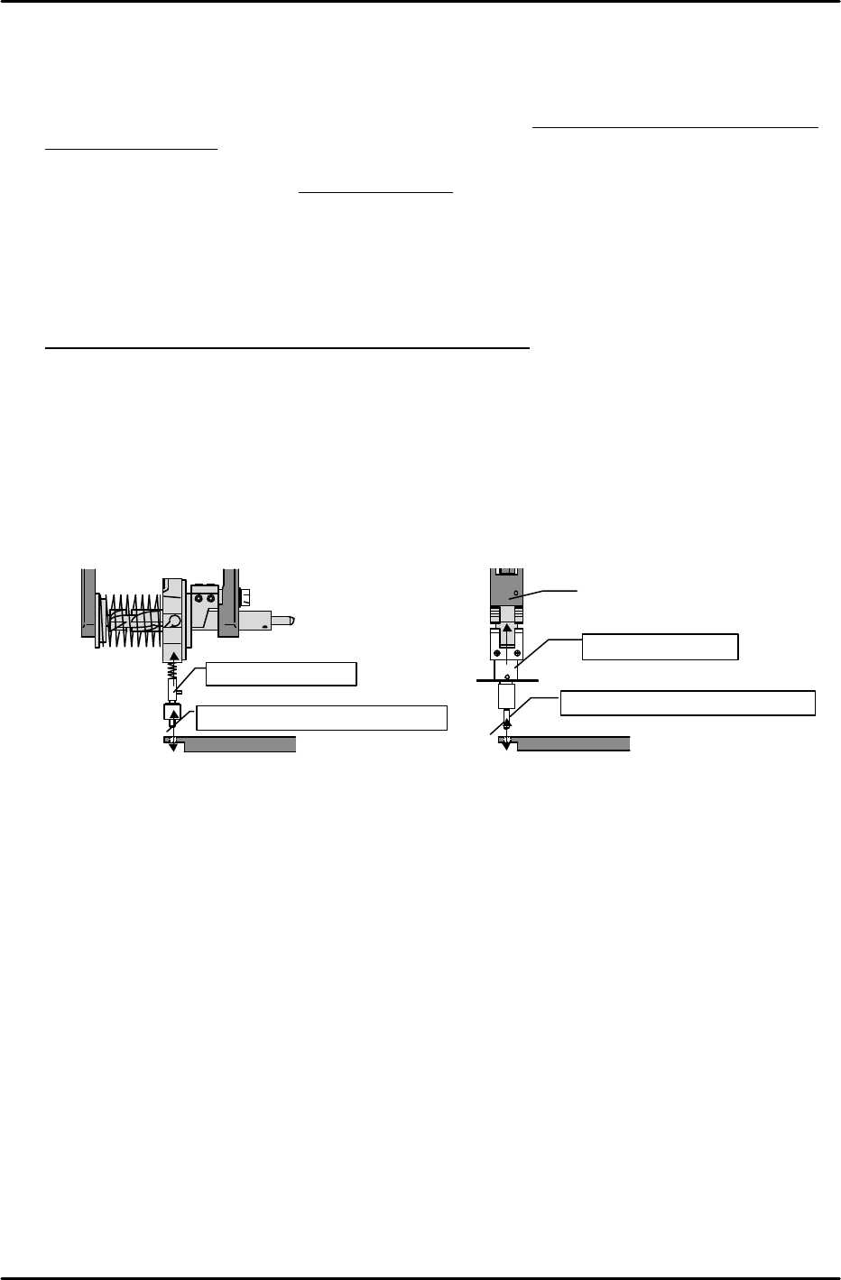
[6-8] Program_Origin_X0,Y0
1) Mount an X0, Y0 Proper data measurement jig in the holder.
2) With the plate jig still clamped as described at [7-7] above, move the head to find the position
where the measurement jig (mounted in holder) can be inserted smoothly into the reference
pin hole.
3) This is the Program_Origin_X0,Y0 position. Execute the following command sequence to
automatically enter this data:
[ETC] à [REF. POS.] à [X0/Y0] à [SET].
Jig for index type
Position where insertion is smooth
Plate jig
Jig for single type
Position where insertion is smooth
Nozzle shaft
Plate jig