QP-242E 工程师培训手册 (6.0).pdf.pdf - 第84页
FK-9F98-07 QP242E Training Text for Service Engineers 6th edition 8. MTU6 Adjustment [ 16 /16] Fuji Machine Mfg. Co., Ltd. Okazaki SMT Equipment Quality Assurance Dept. Technical Support Div. Section No.2 8- 16 *****This…
FK-9F98-07 QP242E Training Text for Service Engineers
6th edition 8. MTU6 Adjustment [15/16]
Fuji Machine Mfg. Co., Ltd. Okazaki
SMT Equipment Quality Assurance Dept.
Technical Support Div. Section No.2
8-15
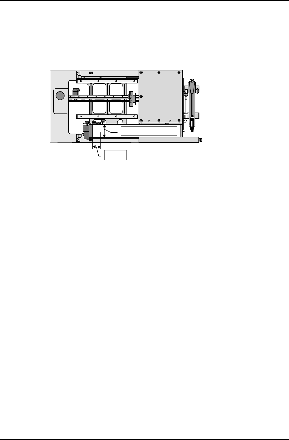
[8-23]
MTU_Parts_Eject_Pos.CV_X,Y
1) Set the nozzle jig.
2) Enable the servo lock status in the position where the center of the tip of the nozzle jig is 50
mm from the center of the reject parts conveyor in the X-direction and 50 mm from the back
side of the conveyor in the Y-direction.
3) This position is the MTU_Parts_Eject_Pos.CV_X & Y position. Use the following command
operation to automatically enter the Proper data; [PROPER], [ETC], [REJECT POS],
[CONVEYOR], and [SET].
[8-24] Proper Data Transmission to F4G
Once measurement of all Proper data items has been completed, transmit theProper data
back to F4G.
★
50mm
Center of the conveyor

FK-9F98-07 QP242E Training Text for Service Engineers
6th edition 8. MTU6 Adjustment [16/16]
Fuji Machine Mfg. Co., Ltd. Okazaki
SMT Equipment Quality Assurance Dept.
Technical Support Div. Section No.2
8-16
*****This page does not contain any contents.
FK-9F98-07 QP242E Training Text for Service Engineers
6th edition 9. Reject Parts Conveyor Adjustment & Operation Check [1/2]
Fuji Machine Mfg. Co., Ltd. Okazaki
SMT Equipment Quality Assurance Dept.
Technical Support Div. Section No.2
9-1
[CHAPTER 9] Reject Parts Conveyor Adjustment
& Operation Check
[9-1]
Prior to Adjusting the Reject Parts Conveyor
There are two types of reject parts conveyors; an L-type (wide) and M-type (narrow).
Furthermore the conveyor is an option and thus all MFUs are not necessarily equipped
with such a conveyor. Check the specification manual or with the Sales department
for the module numbers equipped with a conveyor, the number of conveyors, and the
conveyor type before carrying out work.
Size Belt width Compatible parts
Occupied device
positions
M 33.4 mm 27 ~ 31mm 3
L 78 mm 74 mm 6 (7)
The value in parentheses indicates a conveyor loaded without use of an STU.
The belt width and compatible part size for a reject parts conveyor attached to an MTU6 are both the
same as the data for the L size conveyor.
The belt width of a reject parts conveyor attached to an MTU71 is 54 mm and the compatible part size
is up to 50 mm square.
[9-2] Belt Tension Adjustment
Loosen the motor mount bolts to loosen the chain.
Push in on the belt tension adjustment bolt by 18 to 19 mm and pull the conveyor belt tight.
After the belt tension is adjusted use the motor mount bracket to adjust the chain tension.
[9-3] Part Check Sensor Adjustment
1) Set the part check sensor located on the bottom of the conveyor as indicated below.
2) Move the sensor bracket to adjust the sensor so that it comes on when a 1 mm part is
loaded on the conveyor and goes off when the part is removed.
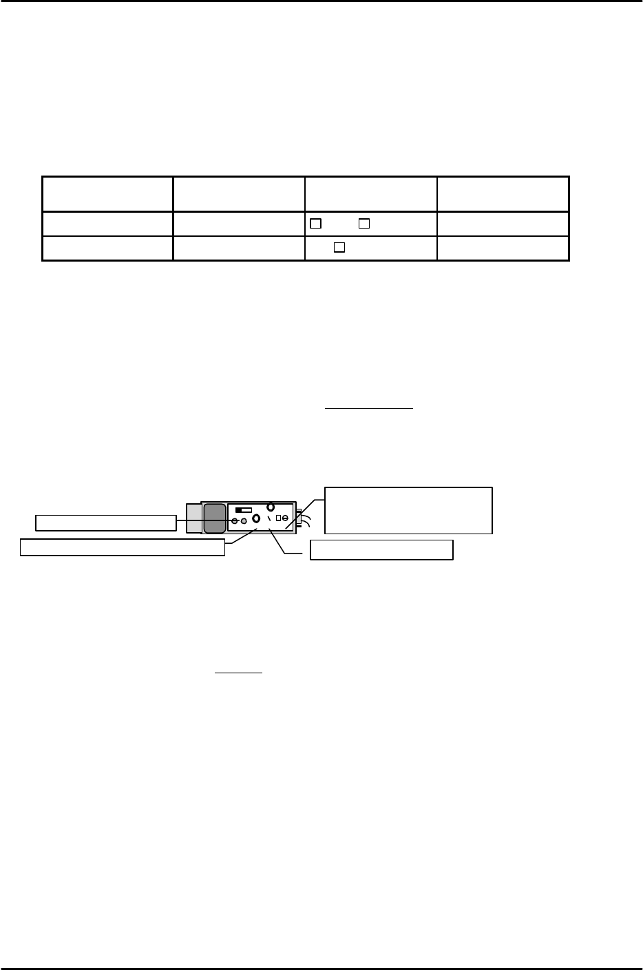
[9-4] Large Part Detection Sensor Adjustment
1) Adjust the sensor up and down so that the distance between the tip of the large parts reject sensor
and the top of the conveyor is 35 mm.
2) Loosen the nut on the large parts reject sensor lens mechanism, turn the lens to a position where
the round red dot of light appears clearly on the reject parts conveyor (in focus), and then tighten
the nut.
3) Set the large part detection sensor amp located on the bottom of the conveyor to “D, ON”, “OFF” and
then set to “Unlock”.
4) Press [SET] with no parts on the conveyor.
5) Load a part on the conveyor and then press [SET]. (Auto-adjustment complete)
6) Then after setting to “Lock”, load a part on the conveyor and check again.
OFF
ALM
OUT
SENS.
TIME.
MODE
0.04 5
5
For reject detection set the
MODE to “5”.
For the TZ-axis set to “1”.
Set the timer to “0.04”.
Set the sensor volume to “Max”.
Set to “ALM.OFF”.
KEYENCE