00194103-01.pdf - 第114页
5 Tasks on the machine User Manual S IPLACE F5 HM 5.3 Carrying out a walk-through inspection Software Version SR.408.xx03/2006 US E dition 114 5.3.2 Splice the t ape in good time PLEAS E NOTE: 5 S plice the tapes early e…
User Manual SIPLACE F5 HM 5 Tasks on the machine
Software Version SR.408.xx 03/2006 US Edition 5.3 Carrying out a walk-through inspection
113
5.3 Carrying out a walk-through inspection
5.3.1 Checking the S feeder modules
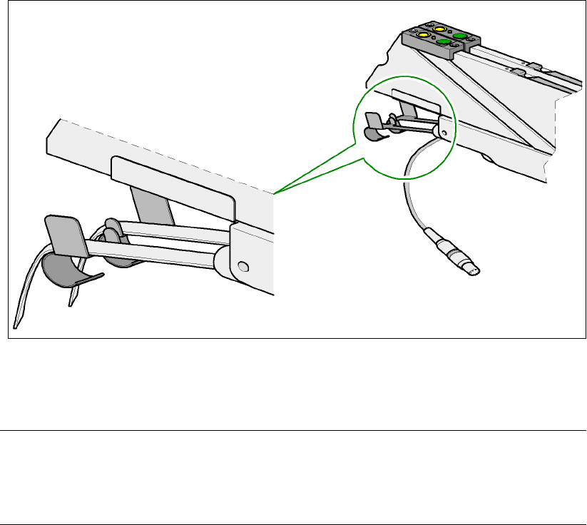
Æ Make sure that the tape is correctly placed in the springs of the S feeder module.
5
Fig. 5.3 - 1Placing the tape in the springs of the S feeder module
Æ Check to see whether the tape foil removal container for the S feeder module is full.
If it is full, then pull out the foil and cut it off with scissors.
PLEASE NOTE
Tearing the foil instead of cutting it can lead problems with the tape removal mechanism.
For this reason the 3 x 8 mm feeder modules are fitted with an integral cutter. This is in the
tape foil removal container at the end of the feeder module under the flaps. 5
Æ Check to see whether the pick-up window of the feeder module has the correct size for the com-
ponent on combination feeder modules (24/32 mm).
Æ Check to see whether tape guides are inserted on combination feeder modules (24/32 mm).

5 Tasks on the machine User Manual SIPLACE F5 HM
5.3 Carrying out a walk-through inspection Software Version SR.408.xx03/2006 US Edition
114
5.3.2 Splice the tape in good time
PLEASE NOTE: 5
Splice the tapes early enough so that the feeders do not become empty. Otherwise you will expe-
rience prolonged down times.
However, do not splice the tapes too early because if you wind the end of the old tape onto the
new reel after splicing, the reel holding the new tape may become overfilled and the tape will slip
off the reel and become tangled up. This will again result in pick-up errors and prolonged down
times.
5.3.3 Check PCB supports
Æ
Check the position of the magnetic PCB supports on the lifting table:
– Make sure that the PCB supports do not collide with components on the underside of the
PCBs.
– In addition, make sure that the PCB supports do not collide with the PCB conveyor pan-
els.
– Only use PCB supports as described in Section 7.13
, page 218.
User Manual SIPLACE F5 HM 5 Tasks on the machine
Software Version SR.408.xx 03/2006 US Edition 5.3 Carrying out a walk-through inspection
115
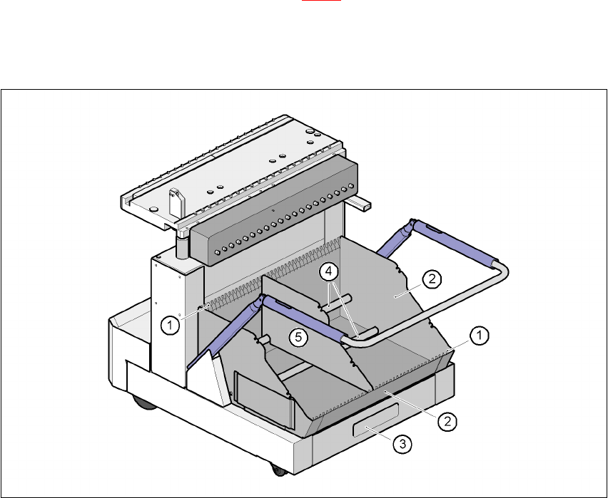
5.3.4 Inserting separating plates in the component trolley tape container
Æ Insert the separating plates as shown in Fig. 5.3 - 2 and remember that the smallest division of
the tape container is a 2x division. This will help avoid placement errors.
Æ Check that the separating plates engage in the same positions on both guide rails. Otherwise
the separating plate will be offset or bent.
5
Fig. 5.3 - 2 Inserting separating plates in the component trolley tape container
(1) Guide rail for the separating plates
(2) Tape container
(3) Waste tape container
(4) Supporting rod for the separating plates
(5) Separating plate