00194103-01.pdf - 第123页
User Manual SIPLAC E F5 HM 5 Tasks on the m achine Software Version S R.408.xx 03/2006 US Edition 5.7 Refilling components 123 5.7 Refilling component s The onl ine help con tains infor mation on ref illing c omponents w…
5 Tasks on the machine User Manual SIPLACE F5 HM
5.6 Avoiding track errors Software Version SR.408.xx03/2006 US Edition
122
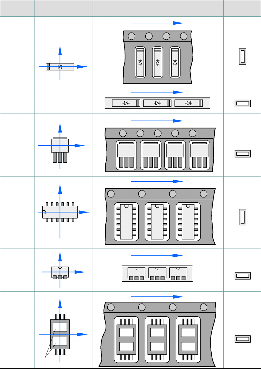
5.6.3 Component coordinate system and pick-up angle
5
Fig. 5.6 - 1 Position of the component and its pick-up angle
Special
component
Stick maga-
zine:
Chip-
components
with polarity
0402
2220
The anode must be
aligned with the +X
coordinate.
Package form Coordinate system
Position in the feeder
Pick-up angle/
nozzle angle
Tape:
SOT 23
Stick maga-
zine:
Tape:
Tape:
SO-IC
DIL-IC
SOT 194
Tape:
Holes
Y
X
Y
X
Y
X
Y
X
Y
X
90°
90°
0°
90°
-90°
0°

User Manual SIPLACE F5 HM 5 Tasks on the machine
Software Version SR.408.xx 03/2006 US Edition 5.7 Refilling components
123
5.7 Refilling components
The online help contains information on refilling components with and without barcodes.
Æ With tape feeder modules, make sure that you always splice on a new tape early enough so
that the feeder modules do not run out of components.
Æ However, do not splice the tapes too early because if you wind the tape onto the new reel after
splicing the end of the old tape, the reel with the new tape may be overfilled. The tape could
then slip off the reel and become tangled. Under certain circumstances, this could cause pick-
up errors and prolonged down times.
Æ Always insert spindles when using tape reels of 15" (381 mm) and larger (see Fig. 5.3 - 3) and
make sure that the separating plates are inserted correctly (see Fig. 5.3 - 3
).
5 Tasks on the machine User Manual SIPLACE F5 HM
5.8 Docking the component trolley in or out Software Version SR.408.xx03/2006 US Edition
124
5.8 Docking the component trolley in or out
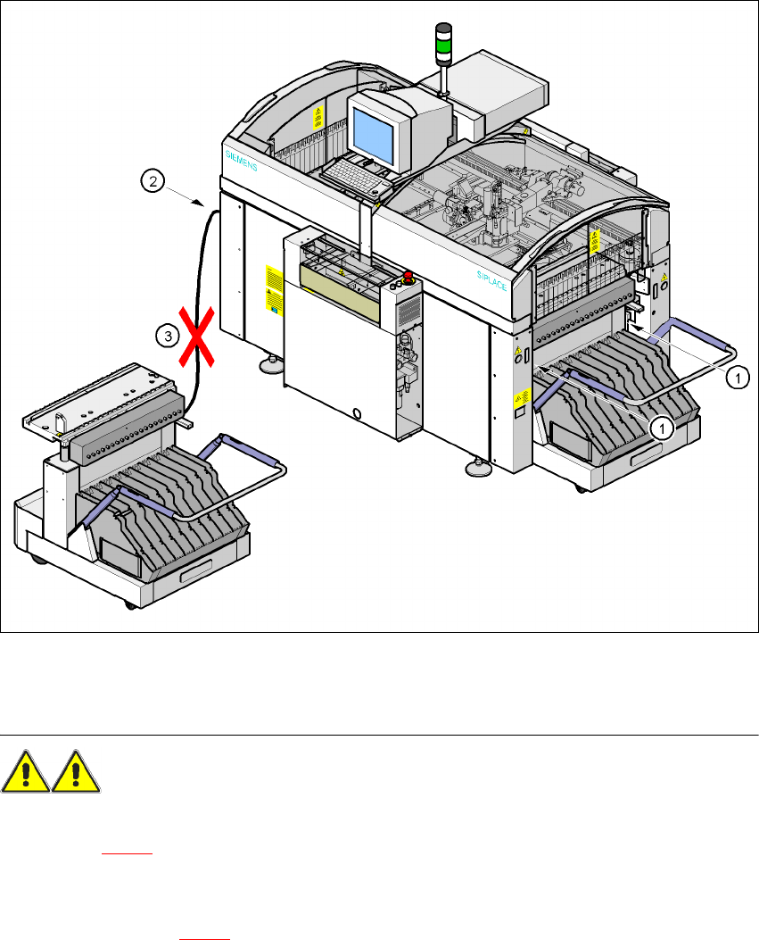
5.8.1 Safety instructions for docking the component trolley in or out
5
Fig. 5.8 - 1 Safety instructions on the component trolley
WARNING 5
Æ Never reach into the gap between the component trolley and the placement system frame (item
1 in Fig. 5.8 - 1
).
Æ Always check that the component trolley is docked on the placement system before connecting
or disconnecting the power cable for the component trolley at the socket on the placement sys-
tem (item 2 in Fig. 5.8 - 1
).