00194103-01.pdf - 第126页
5 Tasks on the machine User Manual S IPLACE F5 HM 5.8 Docking the component trolley in or out Software V ersion SR.408.xx03/2006 US Edition 126 Fig. 5.8 - 2 Docking or undock ing the component trolley (1) Commun ication …

User Manual SIPLACE F5 HM 5 Tasks on the machine
Software Version SR.408.xx 03/2006 US Edition 5.8 Docking the component trolley in or out
125
Æ NEVER connect the connecting cable for the component trolley to the socket on the placement
system and then operate the component trolley outside the machine via the compressed air
control unit (item 3 in Fig. 5.8 - 1
).
Æ Fill locations between the feeder modules with dummy feeder modules (see Section 2.5.5,
page 56).
5 Tasks on the machine User Manual SIPLACE F5 HM
5.8 Docking the component trolley in or out Software Version SR.408.xx03/2006 US Edition
126
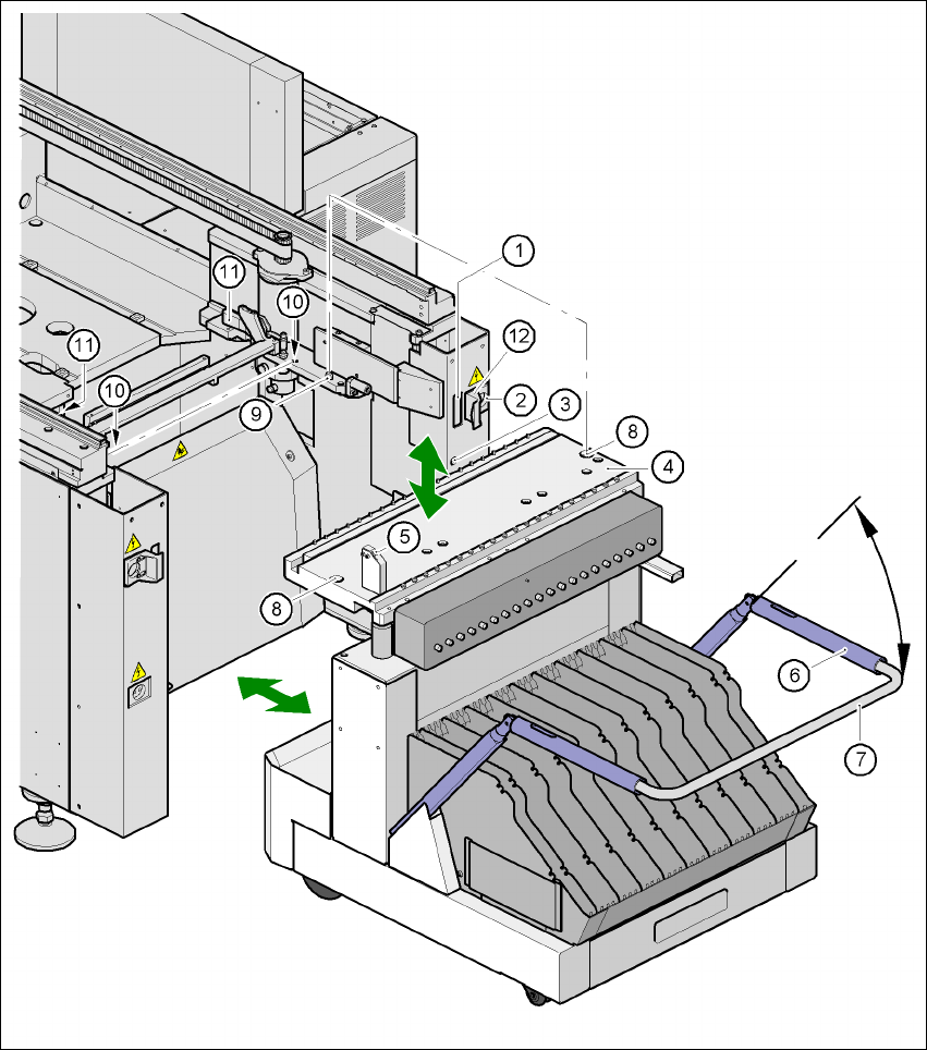
Fig. 5.8 - 2 Docking or undocking the component trolley
(1) Communication interface connector
(2) Power supply connector for the component trolley
(3) Compressed air connection
(4) Component table bed
(5) Button for raising and lowering the component table bed
(6) Actuating tube
(7) Fold-down bracket
User Manual SIPLACE F5 HM 5 Tasks on the machine
Software Version SR.408.xx 03/2006 US Edition 5.8 Docking the component trolley in or out
127
(8) Holes for the centering pins
(9) Centering pin for the component table bed
(10) Contact surfaces for the component table bed (right and left)
(11) Horizontal tensioners
(12) Movable cover that ensures that the power supply and control cables are plugged in and
removed in the correct order.
5
5.8.2 Docking out the component trolley
Æ
Click on the STOP PROCESSING PCB icon in the MAIN VIEW menu.
Æ The PCB in progress will be completed. The icons of the SINGLE FUNCTIONS menu will then
be activated.
Æ Click on the icon SINGLE FUNCTIONS GANTRY.
Æ Click on the GANTRY FUNCTIONS icon.
Æ From this menu, click on the GO TO SET-UP POSITION button.
Æ All the placement heads will move across the PCB conveyor to prevent them being damaged
when the component trolley is changed.
Æ Open protective cover of the selected gantry.
Æ Open the side screens.
Æ Open the horizontal tensioners (item 11 in Fig. 5.8 - 2)
Æ Pull the two actuating tubes (item 6 in Fig. 5.8 - 2) towards you at the same time and lift up the
bracket (item 7 in Fig. 5.8 - 2
). Thus you will lock the raised component table bed in its top end
position.
WARNING DANGER OF CRUSHING 5
When raising the component table bed, never reach into the gap between the feeders and
the used tape channel. 5
Æ Hold down the button (item 5 in Fig. 5.8 - 2) for raising the component table bed (item 4 in Fig.
5.8 - 2
) until the component table bed locks into its top end position.
Æ Unplug the component trolley power cable (item 2 in Fig. 5.8 - 2).
Æ Move the cover (item 12 in Fig. 5.8 - 2) sideways until you can unplug the control cable (item 1
in Fig. 5.8 - 2
).
Æ Unplug the component table control cable (item 1 in Fig. 5.8 - 2).
Æ Unplug the connector for the compressed air supply (item 3 in Fig. 5.8 - 2).
Æ Remove the component trolley.