00194103-01.pdf - 第156页
6 Component handling User Manual S IPLACE F5 H M 6.2 Technical dat a for the S feeder modules Software Version S R.408.xx 03/2006 US Edition 156 6.2.19.2 T echnical dat a Item no. 001 1701 0-xx 6 Assign ed locati ons 3 6…
User Manual SIPLACE F5 HM 6 Component handling
Software Version SR.408.xx 03/2006 US Edition 6.2 Technical data for the S feeder modules
155
6.2.19 Dip module
6
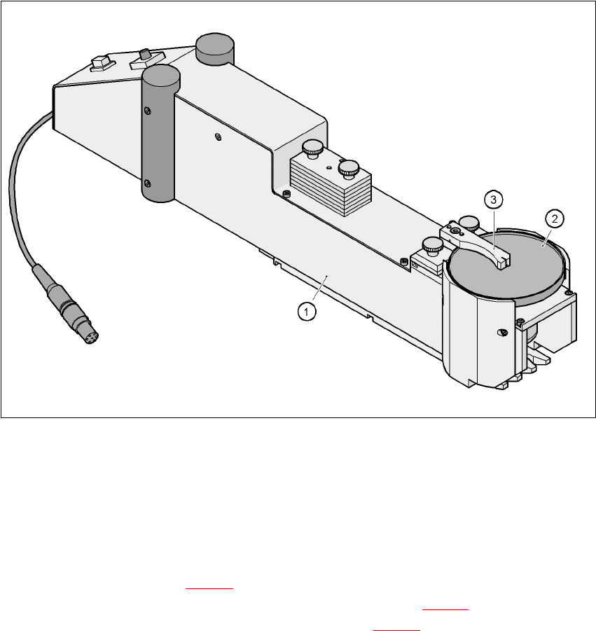
Fig. 6.2 - 19 Dip module
(1)Dip module
(2)Rotating plate
(3)Squeegee
6.2.19.1 Principle of dip fluxing
The dip module (item 1 in Fig 6.2 - 19) is used to wet flip-chip and CSP components with flux or
conductive adhesive. The flux holder is a rotating plate (item 2 in Fig. 6.2 - 19
) on which a thin film
of flux (e.g. 40 µm) is created with a squeegee (item 3 in Fig. 6.2 - 19
). This method is particularly
suitable for highly viscous (honey-like) fluxes. The amount of flux required for the process is re-
duced to a minimum coating thickness since only the undersides of the bumps have to be wetted.
The dip module is suitable for all placement heads. It is regarded as a standalone type of conveyor
by the set-up optimization. There is no limit to the number of dip modules at the individual loca-
tions.
6 Component handling User Manual SIPLACE F5 HM
6.2 Technical data for the S feeder modules Software Version SR.408.xx 03/2006 US Edition
156
6.2.19.2 Technical data
Item no. 00117010-xx 6
Assigned locations 3 6
Component size max. 36 x 36 mm²
depending on the placement head type 6
Possible coating thicknesses 25, 35, 45, 55, 65, 75 µm 6
Time required to change the coating thickness Less than 1 min. 6
Gap height tolerance ± 5 mm 6
Plate rotating speed Set from 0 - 10 sec. with potentiometer
Component dip time Programmable from 0 - 2 sec.
in 0.1 sec. increments 6
Flux Highly viscous flux, conductive adhesive 6
User Manual SIPLACE F5 HM 6 Component handling
Software Version SR.408.xx 03/2006 US Edition 6.3 Component trolley
157
6.3 Component trolley
6.3.1 Structure
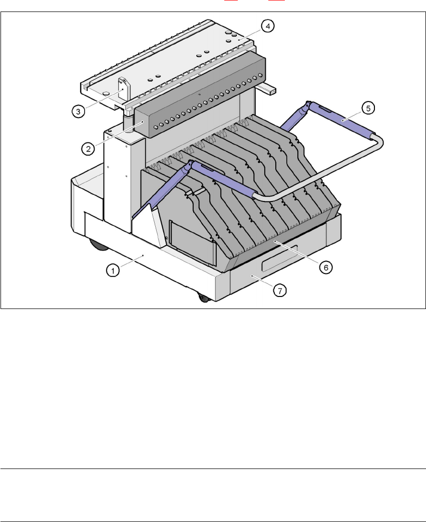
The component trolley consists essentially of a chassis, a component feeder table on which the
feeder is mounted, a communication unit, a tape container and a waste container. Docking the
component trolley in or out is described in Section 5.8
, page 124 onwards.
6
Fig. 6.3 - 1 Component trolley
(1) component trolley
(2) Communication unit
(3) Control button for raising the component feeder table
(4) Component feeder table
(5) Handle for locking and lowering the component feeder table
(6) Tape container
(7) Waste tape container
NOTE ON OPERATIONAL SAFETY 6
All component trolleys must be docked on the machine in order to operate it. If they are not, the
machine stays in EMERGENCY STOP status. The placement process is interrupted. 6