00194103-01.pdf - 第160页
6 Component handling User Manual S IPLACE F5 H M 6.3 Component trolley Software Version S R.408.xx 03/2006 US Edition 160 6 Fig. 6.3 - 4 Connec ting the compressed air supply for bulk case feeders 6 (1) Coupli ng connec …
User Manual SIPLACE F5 HM 6 Component handling
Software Version SR.408.xx 03/2006 US Edition 6.3 Component trolley
159
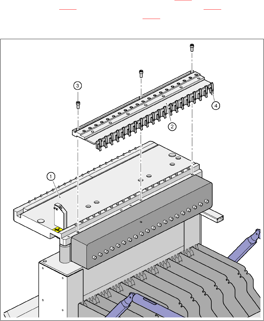
It is easy to fit. Use three screws DIN 912, M8x20 (item 3 in Fig. 6.3 - 3) to fix the compressed air
supply (item 2 in Fig. 6.3 - 3
) to the component feeder table (item 1 in Fig. 6.3 - 3). The com-
pressed air supply has retaining clips (item 4 in Fig. 6.3 - 3
) on the back. They fix the bulk case
feeder modules to the component table and thus ensure a perfect compressed air supply.
6
Fig. 6.3 - 3 Compressed air supply for bulk case feeder modules
(1) Component feeder table
(2) Compressed air supply for bulk case feeder modules
(3) Screw DIN 912, M8x20
(4) Retaining clamp
6 Component handling User Manual SIPLACE F5 HM
6.3 Component trolley Software Version SR.408.xx 03/2006 US Edition
160
6
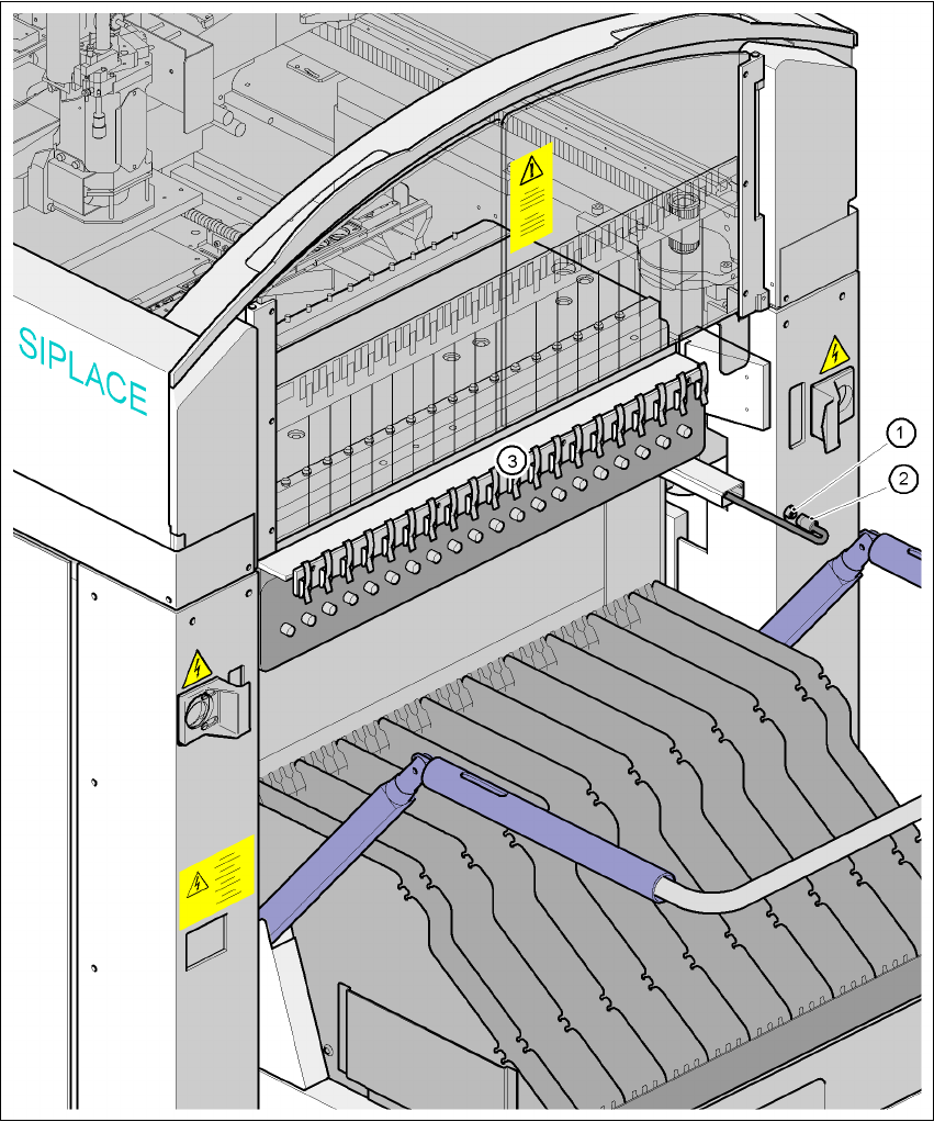
Fig. 6.3 - 4 Connecting the compressed air supply for bulk case feeders
6
(1) Coupling connector for compressed air
(2) Coupling socket with supply hose
(3) Compressed air distributor for bulk case feeder modules
User Manual SIPLACE F5 HM 6 Component handling
Software Version SR.408.xx 03/2006 US Edition 6.3 Component trolley
161
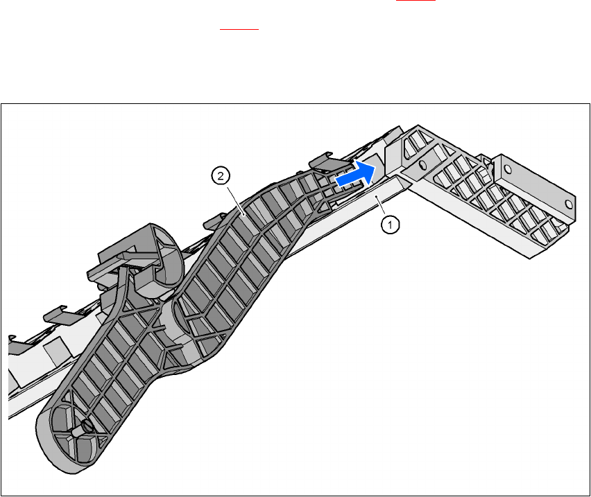
6.3.4 Support for the middle tape reel for 3x 8 mm feeder modules
Type 3x 8 mm S feeders transport components to the pick-up position on three tracks. The tape
reels of the two outer tracks are positioned between the separating plates in the tape container.
The middle tape reel is arranged over the tape reels for the two outer tracks.
For the middle tape reels you will therefore also need:
– 1 adapter plate for holding the tape reel holder (item 1 in Fig. 6.3 - 5
) and
– 1 tape reel holder (item 2 in Fig. 6.3 - 5
) for every two feeders.
The adapter plate is fixed to the component trolley with four fillister head screws, and the tape
reel holders are inserted into the square openings in the adapter plate.
6
Fig. 6.3 - 5 Support for the middle tape reel for 3x 8 mm feeder modules
6
(1) Adapter plate
(2) Tape reel holder