00194103-01.pdf - 第178页
7 Options User Manual SIP LACE F5 HM 7.1 Nozzle changer for the 12-segment C ollect&Place head S oftware Version SR .408.xx 03/2006 US E dition 178 7.1.5 Position detection There is a positio n detec tion fidu cial o…

User Manual SIPLACE F5 HM 7 Options
Software Version SR.408.xx 03/2006 US Edition 7.1 Nozzle changer for the 12-segment Collect&Place head
177
7.1.4 Notes on operation
Æ When you fill a magazine with a certain nozzle type for the first time, attach an adhesive label
to identify the type.
PLEASE NOTE 7
Fill the magazines off the machine and always replace complete magazines. 7
Æ Open the locking plate and place the nozzles in the nozzle garages.
Æ Close the locking plate so that the nozzles cannot drop out of the magazines.
CAUTION 7
Before you fill magazine, make sure that all the nozzles on the Collect&Place head have
been returned to their magazines. 7
Æ Programming the nozzle changer is described in the SIPLACE Pro user manual.
PLEASE NOTE 7
Æ Do not allow components to drop onto the magazines. If they do, they could jam the locking
plate.
Æ Do not allow components to drop onto free feeder module locations. They will stick to the
magnetic bar. Production may have to be interrupted if the feeder modules are not placed on
the component table correctly. You should therefore regularly clean the magazines and free
locations.
7 Options User Manual SIPLACE F5 HM
7.1 Nozzle changer for the 12-segment Collect&Place head Software Version SR.408.xx 03/2006 US Edition
178
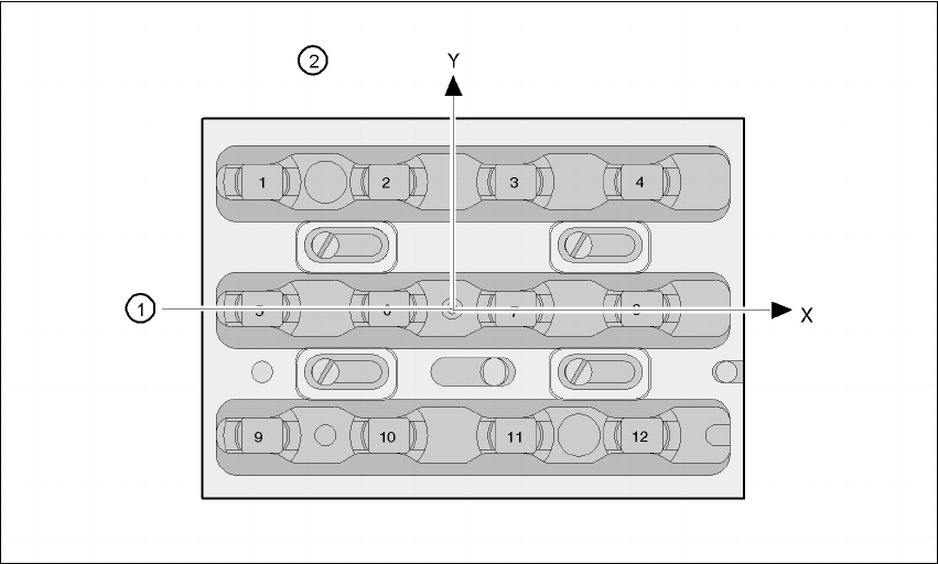
7.1.5 Position detection
There is a position detection fiducial on every magazine.
Fig. 7.1 - 3 Nozzle changer - Position detection
(1) Positioning fiducial
(2) Position of the nozzles in the magazine with respect to the positioning fiducial

User Manual SIPLACE F5 HM 7 Options
Software Version SR.408.xx 03/2006 US Edition 7.2 Nozzle changer for the 6-segment Collect&Place head
179
7.2 Nozzle changer for the 6-segment Collect&Place
head
7.2.1 Overview
A nozzle changer for the 6-segment Collect&Place head may be installed to the left of the PCB
conveyor without losing any locations. This enables the nozzle configuration to be changed
quickly, thus allowing the Collect&Place head to be quickly adapted to the needs of the place-
ment process.
The nozzle changer consists of at least one, and up to five magazines, each with twelve nozzle
garages (see Fig. 7.2 - 1
). The magazines are seated on a common support. Each magazine is
centered using two parallel pins and fixed in place with a spring hook.
Magazines with 9xx or 8xx nozzle types can be set up. The magazines can be arranged as
required.
7.2.2 Technical data - Nozzle changer for the 6-segment Collect&Place head
7
Nozzle changer for the 6-segment Collect&Place head
Dimensions (length x width x height) 575 x 70 x 60 mm³
Number of nozzle garages min. 6 / max. 30
Nozzle types 8 xx, 9 xx
Opening and closing the plate < 200 ms
Capacity of the reject bin approx. 50 nozzles from the 9xx type,
approx. 5 nozzles from the 8xx type
Pneumatic circuit Compressed air line 5.2 bar