00194103-01.pdf - 第181页
User Manual SIPLAC E F5 HM 7 Options Software Version SR.408.xx 03/ 2006 US Edition 7.2 Nozzle changer for the 6-segment Collect&Place head 181 7 Fig. 7.2 - 2 Overview - Magazine and nozzle garage (1) Positi oning f …
7 Options User Manual SIPLACE F5 HM
7.2 Nozzle changer for the 6-segment Collect&Place head Software Version SR.408.xx 03/2006 US Edition
180
7
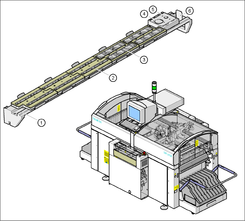
Fig. 7.2 - 1 Nozzle changer for the 6-segment Collect&Place head, overview
(1) Nozzle changer, base
(2) 9xx nozzle magazine
(3) 8xx nozzle magazine
(4) 8xx nozzle discarding device
(5) 9xx nozzle discarding device
(6) Reject bin for discarded nozzles
User Manual SIPLACE F5 HM 7 Options
Software Version SR.408.xx 03/2006 US Edition 7.2 Nozzle changer for the 6-segment Collect&Place head
181
7
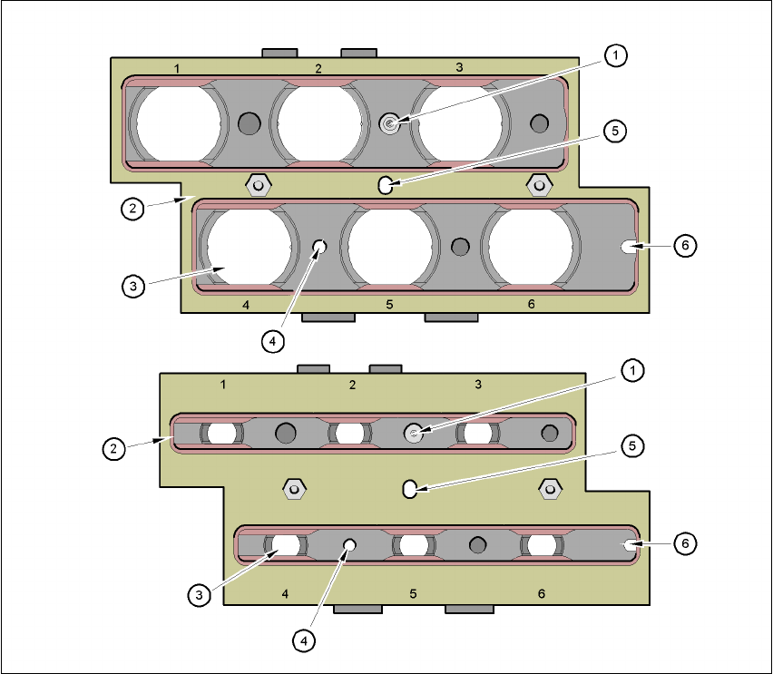
Fig. 7.2 - 2 Overview - Magazine and nozzle garage
(1) Positioning fiducial
(2) Locking plate
(3) 9xx or 8xx nozzle garage
(4) Hole for the parallel pin for centering the magazines
(5) Hole for the parallel pin of the slide mechanism
(6) Slot for the parallel pin for centering the magazines
7.2.3 Mode of operation
The nozzles are seated in nozzle garages and are held in place by a movable locking plate. The
locking plate can be moved 6 mm by a pneumatic cylinder. All the nozzles are either clamped or
released, depending on the position of the plate. The default position of the locking plate, i.e. if
there is no nozzle change in progress, is "closed".

7 Options User Manual SIPLACE F5 HM
7.2 Nozzle changer for the 6-segment Collect&Place head Software Version SR.408.xx 03/2006 US Edition
182
There is a positioning fiducial for position detection on each magazine of the nozzle changer. The
magazine locations are identified by numbers 1 to 5 on the nozzle changer. The nozzle garages
in the magazines are numbered consecutively from 1 to 6 (see Fig. 7.2 - 2
).
PLEASE NOTE 7
Special magazines are available upon request (contact Siemens A&D for details) and will be
numbered differently. 7
Picking up a nozzle
– The Collect&Place head Z axis moves down.
– The locking plate (item 2 in Fig. 7.2 - 2
) opens and releases the nozzles.
– The nozzle is picked up by the sleeve of the Collect&Place head.
– The Z axis moves up.
Setting down a nozzle
– The locking plate (item 2 in Fig. 7.2 - 2) opens and releases the nozzles.
– The Collect&Place head Z axis moves down and sets the nozzle down.
– The locking plate closed.
– The Collect&Place head Z axis moves up.
Discarding defective nozzles
– The Collect&Place head Z axis moves down 14 mm towards the discarding device (items 4
and 5 in Fig. 7.2 - 1
) and thus moves the defective nozzle into the hole in the discarding device.
– The Z axis moves up again and the nozzle is stripped from the sleeve by spring wires.
– The nozzle drops into the used tape channel container (item 6 in Fig. 7.2 - 1
).