00194103-01.pdf - 第185页
User Manual SIPLAC E F5 HM 7 Options Software Version SR.408.xx 03/ 2006 US Edition 7.2 Nozzle changer for the 6-segment Collect&Place head 185 7 Fig. 7.2 - 4 Changing the magazine (1) S pring hoo k (2) Push the spri…
7 Options User Manual SIPLACE F5 HM
7.2 Nozzle changer for the 6-segment Collect&Place head Software Version SR.408.xx 03/2006 US Edition
184
7.2.5 Emptying the reject bin
The capacity of the reject bin is approx. 50 nozzles for nozzle family 9xx and approx. 5 nozzles
for nozzle family 8.xx. To avoid interruption of the placement sequence, you should regularly
empty the reject bin.
Fig. 7.2 - 3 Emptying the reject bin
(1) Remove the reject bin
Æ Pull the reject bin out of its retainer in the direction indicated by the arrow, and lift the bin out
of its holder.
Æ To return the reject bin, push it back into the retainer.
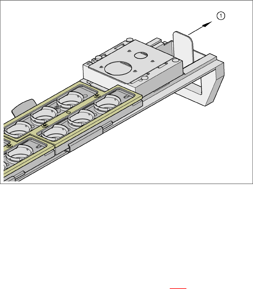
7.2.6 Changing the magazine
Æ To remove the magazine, push the spring hook (item 1 in Fig 7.2 - 4) to the side and lift the
magazine out of the carrier.
User Manual SIPLACE F5 HM 7 Options
Software Version SR.408.xx 03/2006 US Edition 7.2 Nozzle changer for the 6-segment Collect&Place head
185
7
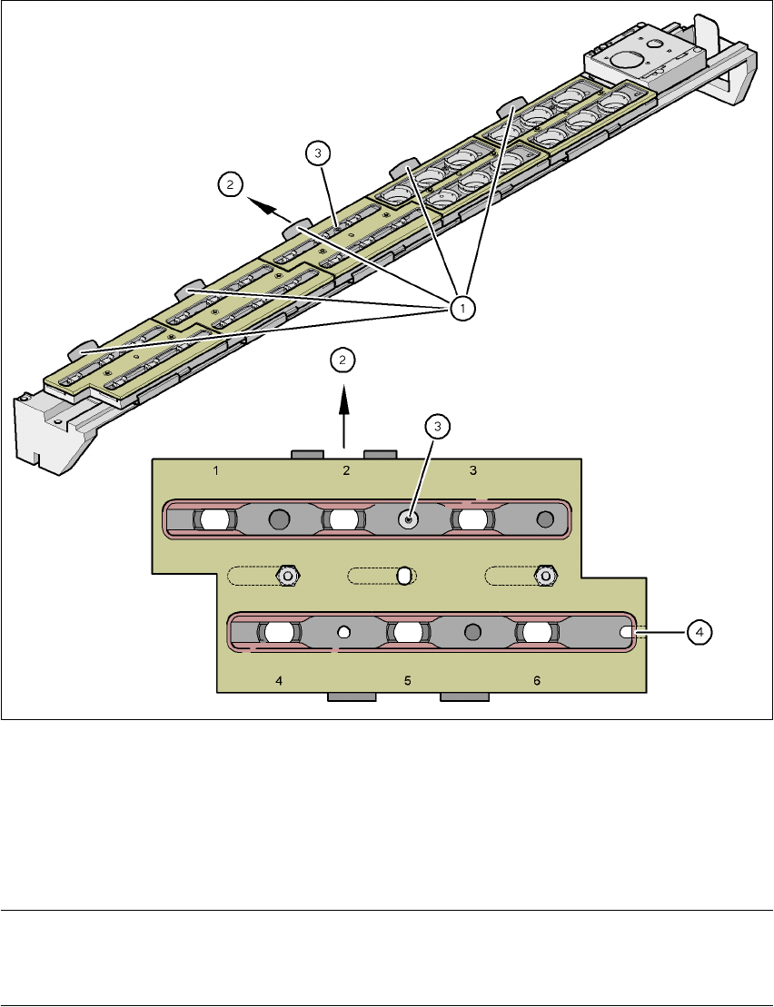
Fig. 7.2 - 4 Changing the magazine
(1) Spring hook
(2) Push the spring hook aside.
(3) Positioning fiducial
(4) Latching groove
PLEASE NOTE
When you insert the magazine, make sure that the side with the position fiducial points towards
the spring hook. There is a latching groove on the opposite side of the magazine. 7
Æ To insert the magazine, place the side with the groove on the tray.
Æ Push the spring hook to one side and click the entire magazine onto the carrier.
Release the spring hook.
The spring hook must latch into place.
7 Options User Manual SIPLACE F5 HM
7.3 Component barcode Software Version SR.408.xx 03/2006 US Edition
186
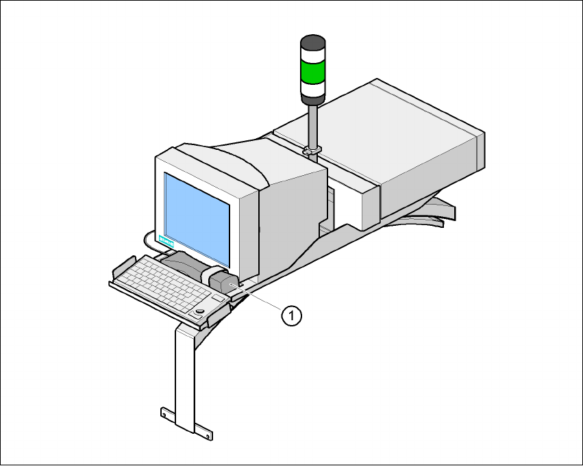
7.3 Component barcode
7.3.1 General
With the placement system, a barcode scanner can be used to check that the track allocation is
correct and to read component data from component reels.
7
Fig. 7.3 - 1 Component barcode scanner
(1) Component barcode scanner
Track allocation
Four-digit barcode strips are attached to the lateral safety screens for the purposes of track allo-
cation. The first digit is used to identify the component table (1 or 2), while the remaining three
digits specify the track number. There are also return barcodes at both ends of the barcode strip.
The barcode strips are numbered consecutively in intervals of two (1, 3, 5, 7...) and each repre-
sents 2 tracks (barcode 1 = track 1 and 2).