00194103-01.pdf - 第187页
User Manual SIPLAC E F5 HM 7 Options Software Vers ion SR.408.xx 03/2006 U S Edition 7.3 Component b arcode 187 Components Data can be r ead from t he compon ent reels to compare the stoc k of comp onents agains t the qu…
7 Options User Manual SIPLACE F5 HM
7.3 Component barcode Software Version SR.408.xx 03/2006 US Edition
186
7.3 Component barcode
7.3.1 General
With the placement system, a barcode scanner can be used to check that the track allocation is
correct and to read component data from component reels.
7
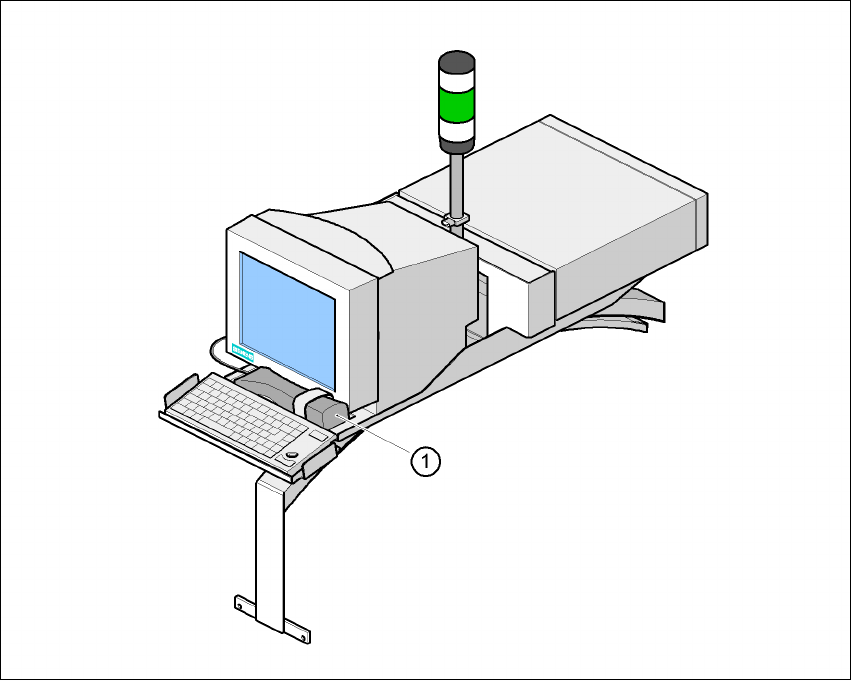
Fig. 7.3 - 1 Component barcode scanner
(1) Component barcode scanner
Track allocation
Four-digit barcode strips are attached to the lateral safety screens for the purposes of track allo-
cation. The first digit is used to identify the component table (1 or 2), while the remaining three
digits specify the track number. There are also return barcodes at both ends of the barcode strip.
The barcode strips are numbered consecutively in intervals of two (1, 3, 5, 7...) and each repre-
sents 2 tracks (barcode 1 = track 1 and 2).

User Manual SIPLACE F5 HM 7 Options
Software Version SR.408.xx 03/2006 US Edition 7.3 Component barcode
187
Components
Data can be read from the component reels to compare the stock of components against the
quantity specified in the set-up file (refill check), for example.
An audible signal is given when each dataset has been read successfully.
PLEASE NOTE 7
The component barcode scanner option must be configured on the SIPLACE Pro computer.
Barcodes that start with the number 1 or 2 and are less than 5 digits long are interpreted as track
barcodes. All other barcodes (that do not start with number 1 or 2 and are more than 5 characters
long) are interpreted as component barcodes. 7
7.3.2 Technical data
7
Connection Station computer
Data entry via barcode scanner or keyboard
Number of characters up to 40
Not permissible Barcodes starting with a 1 or 2 and less than 5
characters long
Number of barcodes up to 6 per component
Filter for suppressing data up to 1 per barcode
Preset code types Code 39 (standard or ASCII)
Code 2 of 5, interleaved and normal,
Code 128, UPC/EAN/JAN codes
(others available upon request)
7 Options User Manual SIPLACE F5 HM
7.4 PCB barcode Software Version SR.408.xx 03/2006 US Edition
188
7.4 PCB barcode
7.4.1 Overview
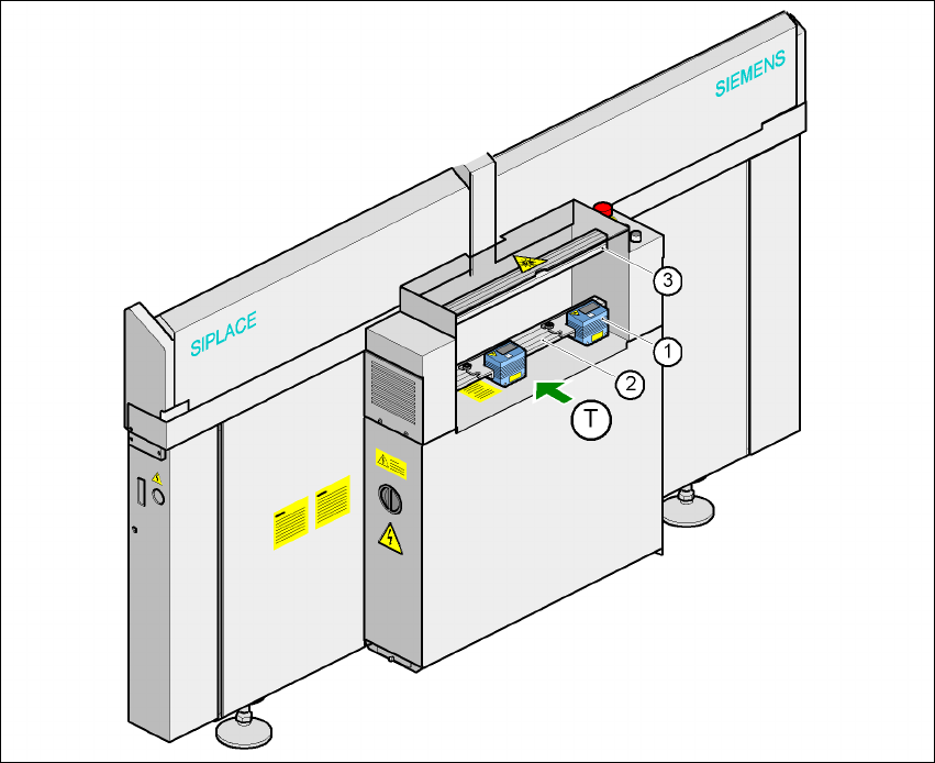
The PCB barcode scanner is used to automatically record and decode barcodes on PCBs. The
PCB barcode scanner sends the read data via its serial interface to the machine controller for fur-
ther processing.
The PCB barcode scanners are installed on the input side of the placement machine, above and
below the PCB conveyor, so that barcode labels on the topside and underside of the PCBs can
be read.
One or two PCB barcode scanners may be retrofitted in order to read the topside and underside
of the PCB on the transport track.
7
Fig. 7.4 - 1 Position of the modules on the input side of the placement machine
(1) Barcode scanning head
(2) Profiled rail for ‘underside’ PCB barcode scanner
(3) Profiled rail for ‘topside’ PCB barcode scanner