00194103-01.pdf - 第189页
User Manual SIPLAC E F5 HM 7 Options Software Version SR.408.xx 03/2006 US Edition 7.4 PCB barcode 189 The PCB barcode s canners ar e fixed to the top an d bottom pr ofiled rai l using retainers. T hese can b e positio n…
7 Options User Manual SIPLACE F5 HM
7.4 PCB barcode Software Version SR.408.xx 03/2006 US Edition
188
7.4 PCB barcode
7.4.1 Overview
The PCB barcode scanner is used to automatically record and decode barcodes on PCBs. The
PCB barcode scanner sends the read data via its serial interface to the machine controller for fur-
ther processing.
The PCB barcode scanners are installed on the input side of the placement machine, above and
below the PCB conveyor, so that barcode labels on the topside and underside of the PCBs can
be read.
One or two PCB barcode scanners may be retrofitted in order to read the topside and underside
of the PCB on the transport track.
7
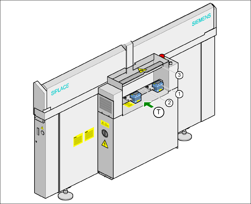
Fig. 7.4 - 1 Position of the modules on the input side of the placement machine
(1) Barcode scanning head
(2) Profiled rail for ‘underside’ PCB barcode scanner
(3) Profiled rail for ‘topside’ PCB barcode scanner

User Manual SIPLACE F5 HM 7 Options
Software Version SR.408.xx 03/2006 US Edition 7.4 PCB barcode
189
The PCB barcode scanners are fixed to the top and bottom profiled rail using retainers. These
can be positioned as required on the profiled rails, and aligned with respect to the barcode
labels. Depending on the position of the barcode strips, the barcode scanner can be attached in
a few simple steps so that the strips can be read parallel to or across the PCB transport direction.
7.4.2 Warning label W216 on the cover of the PCB input side
7
Warning label W216 "Laser class 2" on the cover of the PCB input side,
item no. 03010316-01 (number per placement machine: 1)
PLEASE NOTE 7
When you install a PCB barcode scanner on the placement machine, you must attach laser
warning label W206 contained in the retrofit kit to the cover on the PCB input side.
7.4.3 Description of the functions
7.4.3.1 PCB barcode scanner for the single conveyor
The SIPLACE PCB barcode scanner supports the flexible manufacture of SMD products, and
increases placement reliability. It recognizes all the code types conventionally used in industrial
applications.
The laser scanner reads the barcode label on the topside or underside of each incoming PCB as
they are transported onto the input conveyor. The SIPLACE Pro computer uses the barcode
information to automatically select the right placement program from the previously created bar-
code assignment list (BA list), and sends it to the station. If a barcode filter is defined, only infor-
mation that is identified as relevant within the barcode is compared. This procedure is carried out
time neutrally during placement of the PCB already in the machine. If several PCBs with the
same barcode enter in succession, the program is only transferred the first time. The following
requirements apply to all products to be produced using the PCB barcode:
– The component set-up must be identical on all the machines on the line
– All PCBs must be of the same width
7
7
7
7
7
7
LASER RADIATION!
Do not look into beam
Laser class 2

7 Options User Manual SIPLACE F5 HM
7.4 PCB barcode Software Version SR.408.xx 03/2006 US Edition
190
7.4.3.2 PCB barcode scanner for the dual conveyor
On the dual conveyor, the PCB barcode is only used to transfer the barcode via the GEM inter-
face. This is absolutely essential. The placement program cannot be supplied automatically.
7.4.4 Technical data
7
7
* This value can only be achieved if the barcode label on the PCB passes through the scanner
perpendicular to the machine’s transport direction.
**The position of the barcode scanner on the input conveyor can be easily adjusted, depending
on where the barcode labels are located on the PCBs.
Max. component sizes for the single
conveyor
Standard: (L x W) up to 460 x 460 mm²
Option: (L x W) up to 508 x 460 mm²
(same width for all the jobs in a sequence)
Label dimensions Stroke width B: 0.19 < W ≤ 0.3 mm
(corresponds to high and medium density)
Stroke length: ≥ 4 mm*
Length of the barcode template window: ≤ 90 mm
Label alignment on the PCB ** Parallel or perpendicular with respect to the PCB
transport direction,
as close as possible to the stationary PCB transport
side.
Label colors (contrast ratio > 70% to DIN
66236)
Coding: black, dark green, dark blue
Background: white, beige, yellow, orange
Code types Code 39, Code 128 / EAN 128,
Codabar, 2/5 IATA 2/5 industrial,
2/5 interleaved, UPC, EAN,
Pharma Code, EAN Addendum
(others available upon request)
Complete barcode Up to 25 digits (a barcode filter can also be defined)
Laser scanner safety Laser diode 670 nm (red) / 1 mW
Laser protection class 2, type of protection IP65
Scanning / analysis duration Time neutral (T ≤ 1 s), since it is carried out in parallel
to placement of the previous PCB