00194103-01.pdf - 第198页
7 Options User Manual SIP LACE F5 HM 7.6 Multicolor PCB camera (type 18) Software Version SR.408.xx 03/2006 US Edition 198 – Blue o blique l ighting: In most c ases, thi s can be used to grea tly impr ove the con trast w…
User Manual SIPLACE F5 HM 7 Options
Software Version SR.408.xx 03/2006 US Edition 7.6 Multicolor PCB camera (type 18)
197
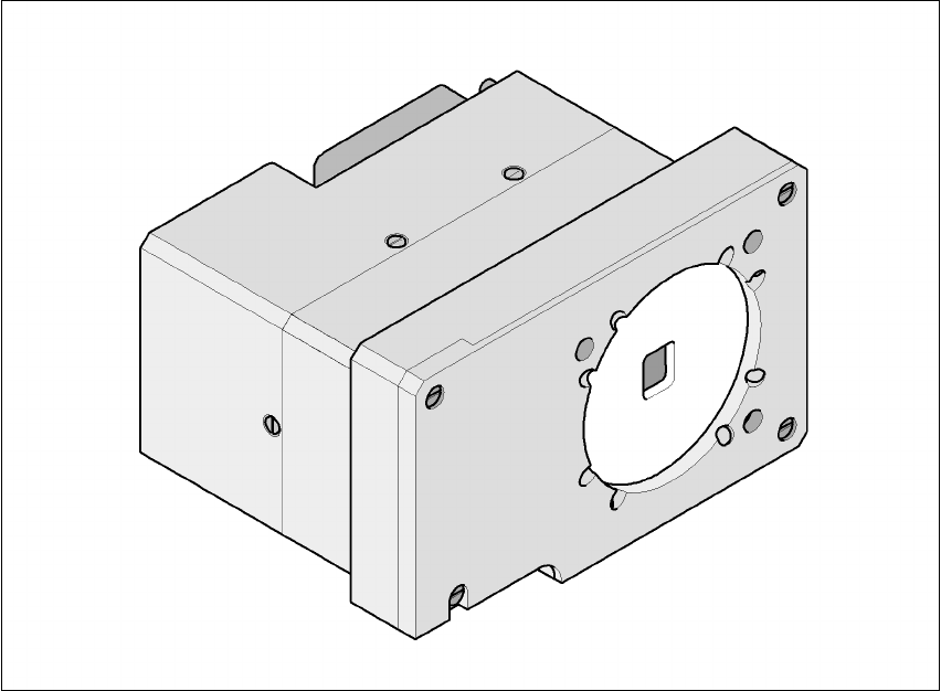
7.6 Multicolor PCB camera (type 18)
7.6.1 General
As an option, a multicolor PCB camera can be installed in place of the sub-gantry camera. The
multicolor PCB camera offers four different types of illumination. This greatly increases fiducial de-
tection and thus the centering accuracy.
7
Fig. 7.6 - 1 Multi-color PCB camera
7.6.2 Types of illumination for the multicolor PCB camera
The following types of illumination can be selected on the multicolor PCB camera:
– Standard lighting
This mixture of white and infrared lighting can be used to detect a broad range of fiducials. The
image contrast can be improved by varying the illumination, thus optimizing the centering of
different fiducials.
– White lighting
This type of illumination is used for standard PCBs with tinned fiducials.

7 Options User Manual SIPLACE F5 HM
7.6 Multicolor PCB camera (type 18) Software Version SR.408.xx 03/2006 US Edition
198
– Blue oblique lighting:
In most cases, this can be used to greatly improve the contrast with bright fiducials on a light
base material, such as ceramic or CEM (c
omposite electrochemical materials). Fiducials cov-
ered with solder resist can also be detected better on a light background.
– Infrared lighting
This type of illumination is particularly useful for fiducials that are covered with solder resist or
for fiducials on flex materials. It is also sometimes possible to improve detection of silver/plat-
inum fiducials on ceramic. This should be tested by carrying out a test centering or placement
run.
User Manual SIPLACE F5 HM 7 Options
Software Version SR.408.xx 03/2006 US Edition 7.7 Nozzle changer for the Pick&Place head
199
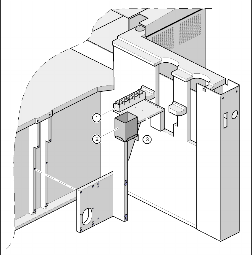
7.7 Nozzle changer for the Pick&Place head
7.7.1 Overview
Fig. 7.7 - 1 Installation location of the nozzle changer for the Pick&Place head
(1) Magazine for 5 nozzles
(2) Reject bin
(3) Support plate