00194103-01.pdf - 第200页
7 Options User Manual SIP LACE F5 HM 7.7 Nozzle changer for the Pick&Place head Software Version SR.408.xx 03/2006 US Edition 200 The SIPL ACE F5 HM placem ent machi ne is equ ipped with a noz zle changer for the Pic…
User Manual SIPLACE F5 HM 7 Options
Software Version SR.408.xx 03/2006 US Edition 7.7 Nozzle changer for the Pick&Place head
199
7.7 Nozzle changer for the Pick&Place head
7.7.1 Overview
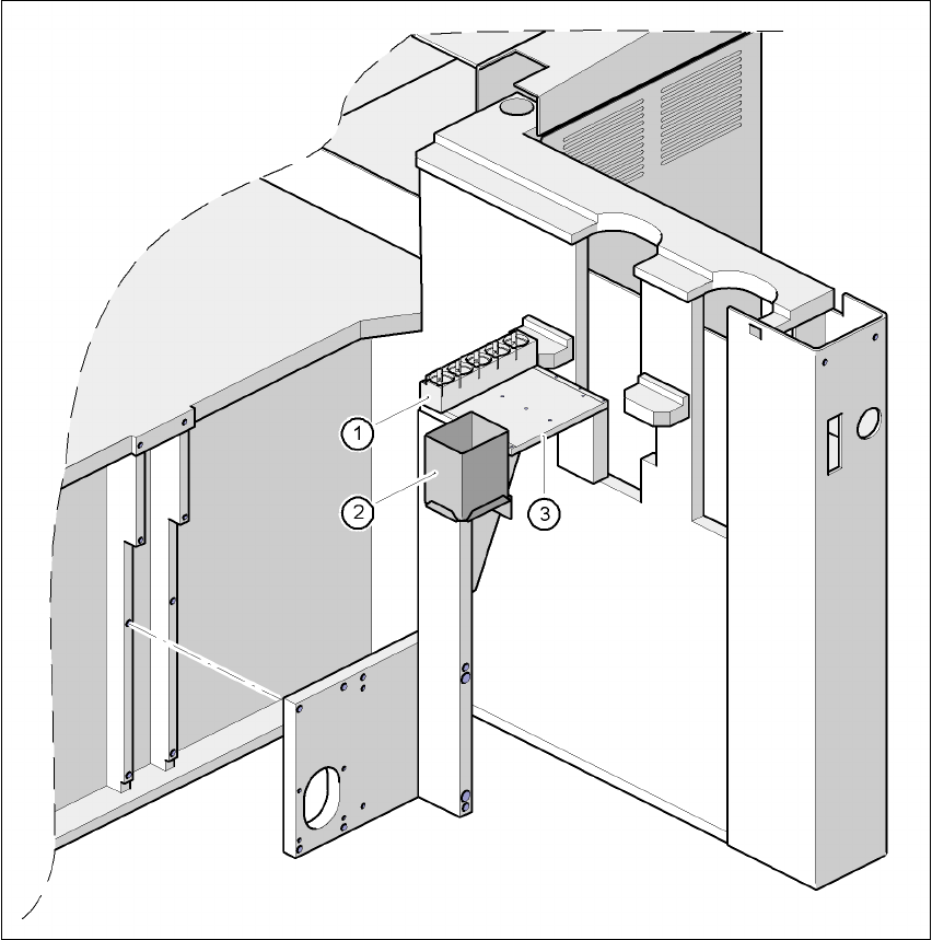
Fig. 7.7 - 1 Installation location of the nozzle changer for the Pick&Place head
(1) Magazine for 5 nozzles
(2) Reject bin
(3) Support plate
7 Options User Manual SIPLACE F5 HM
7.7 Nozzle changer for the Pick&Place head Software Version SR.408.xx 03/2006 US Edition
200
The SIPLACE F5 HM placement machine is equipped with a nozzle changer for the Pick&Place
head as standard. It is supplied with a nozzle magazine for five nozzles, for example four stan-
dard nozzles from the 4xx series and one special nozzle. Three additional nozzle magazines
may be retrofitted if required, providing up to 20 nozzles.
7.7.2 Technical data - Nozzle changer for the Pick&Place head
7.7.3 Description of the functions
7
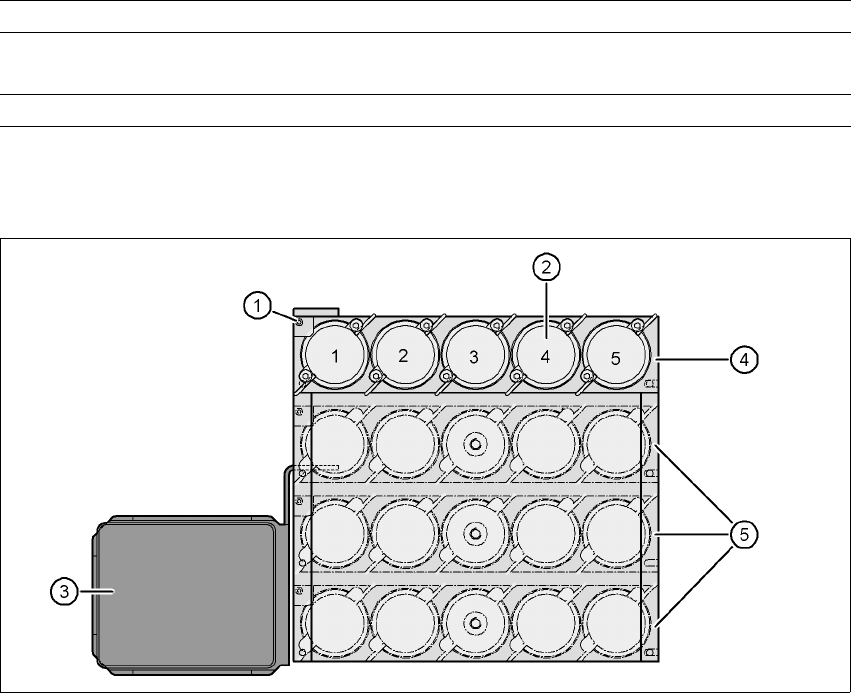
Fig. 7.7 - 2 Nozzle changer overview
7
Nozzle types All nozzles from the 4xx series, special nozzle (optional)
Capacity 1 to 4 magazines, each with 5 nozzles, may be configured as
required
Nozzle changeover time approx. 2 sec. per nozzle
(1) Positioning fiducial
(2) Nozzle garage
(3) Reject bin
(4) Magazine 1 (standard)
(5) Magazine 2 to 4 (optional)
User Manual SIPLACE F5 HM 7 Options
Software Version SR.408.xx 03/2006 US Edition 7.7 Nozzle changer for the Pick&Place head
201
– There is a positioning fiducial for position detection on each magazine of the nozzle changer
(item 1
in Fig. 7.7 - 2
).
– The individual locations are numbered consecutively from 1 to 4.
– The individual nozzle garages in the individual magazines are numbered consecutively from 1
to 5.
– The nozzles are fixed in position in the holder using sprung hooks. The nozzles are either
clamped or released according to the direction of rotation of the Pick&Place head axis.
7.7.4 Notes on operation and maintenance
Æ
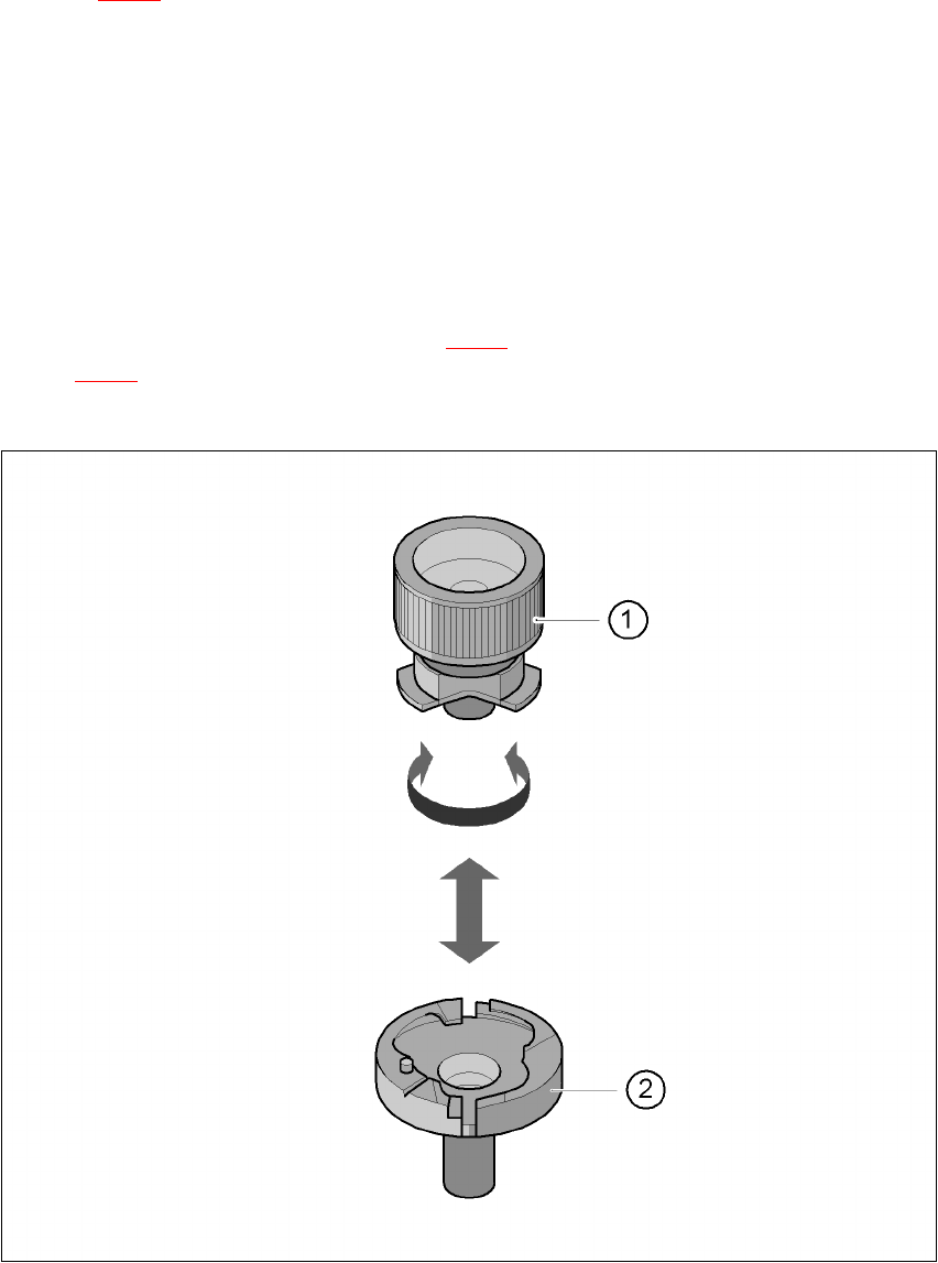
Use the nozzle removal tool (item 1 in Fig. 7.7 - 3) to insert and change the nozzles (item 2 in
Fig. 7.7 - 3
).
Æ Clean the nozzle changer as described in the preventive maintenance instructions.
7
Fig. 7.7 - 3 Remove nozzle from the nozzle changer