00194103-01.pdf - 第205页
User Manual SIPLAC E F5 HM 7 Options Software Version SR.408.xx 03/ 2006 US Edition 7.9 Coplanarity laser module 205 The cop lanarit y laser mo dule is combined with optic al compo nent cente ring , and is u sed in a vis…
7 Options User Manual SIPLACE F5 HM
7.9 Coplanarity laser module Software Version SR.408.xx 03/2006 US Edition
204
7.9 Coplanarity laser module
7.9.1 Description of the functions
The coplanarity laser module is used to measure vertical bending of the leads. The lead length is
measured without contact using the laser triangulation principle.
The placement head picks up the component to be checked, centers it optically using the IC
camera and moves all four sides one after another over the fixed laser beam of the coplanarity
laser module. In this way, every lead is scanned from below by the laser beam. The laser light
scattered by the underside of the lead is recorded by a sensor, and is then used to calculate the
exact position of the lead with respect to the PCB. The position values thus calculated are com-
pared against the limit value specified by the user. If they exceed this value, the component is
disposed of or returned.
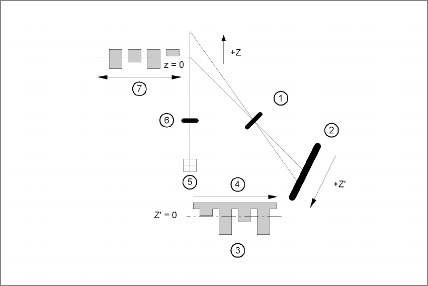
Fig. 7.9 - 1 Laser triangulation measurement principle
(1) Receiver lens (2) Detector
(3) Measuring signal (4) Time t
(5) Laser (6) Transmitter lens
(7) Travel direction
User Manual SIPLACE F5 HM 7 Options
Software Version SR.408.xx 03/2006 US Edition 7.9 Coplanarity laser module
205
The coplanarity laser module is combined with optical component centering, and is used in a
vision module. Components with bent or missing leads are detected and disposed of, if neces-
sary.
7.9.2 Technical data
Component range: Can be used for ’gull wing’ package forms, spacing > 0.3 mm
and maximum component size 55 x 55 mm². Other restric-
tions are associated with the machine configuration.
Measuring principle: Contact-free measurement by laser triangulation
Algorithm functions: JEDEC standard - calculation of the placement plane; all
deviations are determined in relation to this plane. If the com-
ponent is angled with respect to the vacuum nozzle, as can
happen if an adapter is used, then it will have no influence
over the choice between ‘good’ and ‘bad’.
Measuring range: 3 mm
Start of measuring range (SMR) 24 mm
Reference distance
Middle of measuring range (MMR) 25.5 mm
End of measuring range (EMR) 27 mm
Linearity ± 1.5 µm
Resolution: 0.15 µm
Measuring rate 10 kHz
Wave length 670 nm, red
Max. output 1 mW
Laser class 2
Permissible ambient light: 30,000 lx
Light spot diameter SMR 80 µm, MMR 35 µm, EMR 80 µm
Operating temperature: 0°C ... + 50°C
Storage temperature - 20°C ... + 70°C
Sensor protection class IP 65
Supply voltage 24 VDC (± 15%, max. 500 mA)
Output, digital RS 422, 687.5 kBaud
Electromagnetic
compatibility (EMC)EN 50081-1 and EN 61000-6-2
Vibration 2 g / 20 ... 500 Hz
Mechanical shock 15 g / 6 ms
Weight of sensor approx. 0.5 kg
7 Options User Manual SIPLACE F5 HM
7.9 Coplanarity laser module Software Version SR.408.xx 03/2006 US Edition
206
7.9.3 Safety instructions
The sensor works with a semiconductor laser of wave length 670 nm (visible/red).
The maximum optical output is £ 1 mW.
The sensor is classified as laser class 2.
– When operating the sensor, always follow the relevant regulations of VDE 0837 concerning
"Radiation safety for laser equipment" and German accident prevention regulation entitled
"Laser radiation" (VBG 93).
– Also follow the accident prevention regulations applicable in your country.
As a precautionary measure, an audible or visual warning should be emitted to signal that the la-
ser is in use.
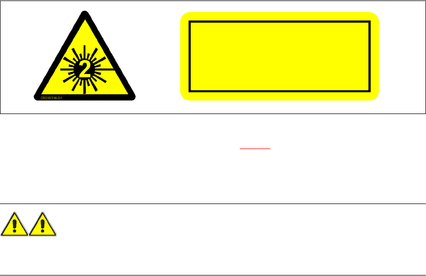
The following information plates are attached to the front and back of the sensor housing:
7
Fig. 7.9 - 2 Identification of laser class 2 for the sensor
The working laser is signaled by an LED (see Section 7.9.4.2).
NEVER look directly into the laser beam, despite the low laser output. The beam is visible, so the
eyes will be protected by the natural eyelid-closing reflex.
WARNING 7
Only authorized personnel may open the housing of the optical sensor.
For repair and servicing, always return the sensors to SIEMENS A&D.
7
7
LASER RADIATION
DO NOT LOOK INTO BEAM
LASER CLASS 2 PRODUCT
P ≤ 1 mW λ = 670 nm