00194103-01.pdf - 第210页
7 Options User Manual SIP LACE F5 HM 7.10 DCA v ision camera Software Version SR.408.xx 03/2006 US Edition 210 7.10 DCA vision camer a 7.10.1 Struc ture Fig. 7.10 - 1 DCA v ision camera 7 (1) DCA visi on ca mera, le ns a…
User Manual SIPLACE F5 HM 7 Options
Software Version SR.408.xx 03/2006 US Edition 7.9 Coplanarity laser module
209
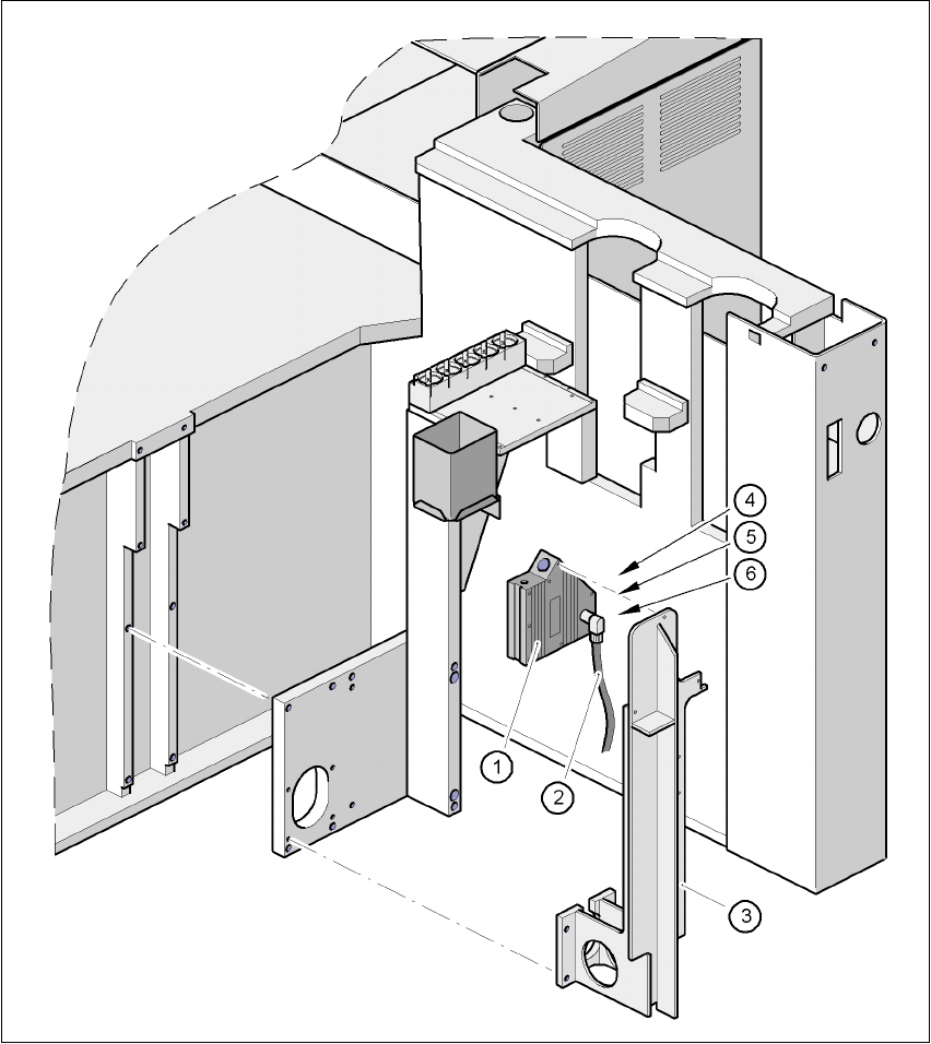
Fig. 7.9 - 4 Coplanarity module
(1) Laser module
(2) Connecting cable
(3) Supporting frame
(4) Red LED: OUT OF RANGE
(5) Red LED: POOR TARGET
(6) Green LED: LASER ON
7 Options User Manual SIPLACE F5 HM
7.10 DCA vision camera Software Version SR.408.xx 03/2006 US Edition
210
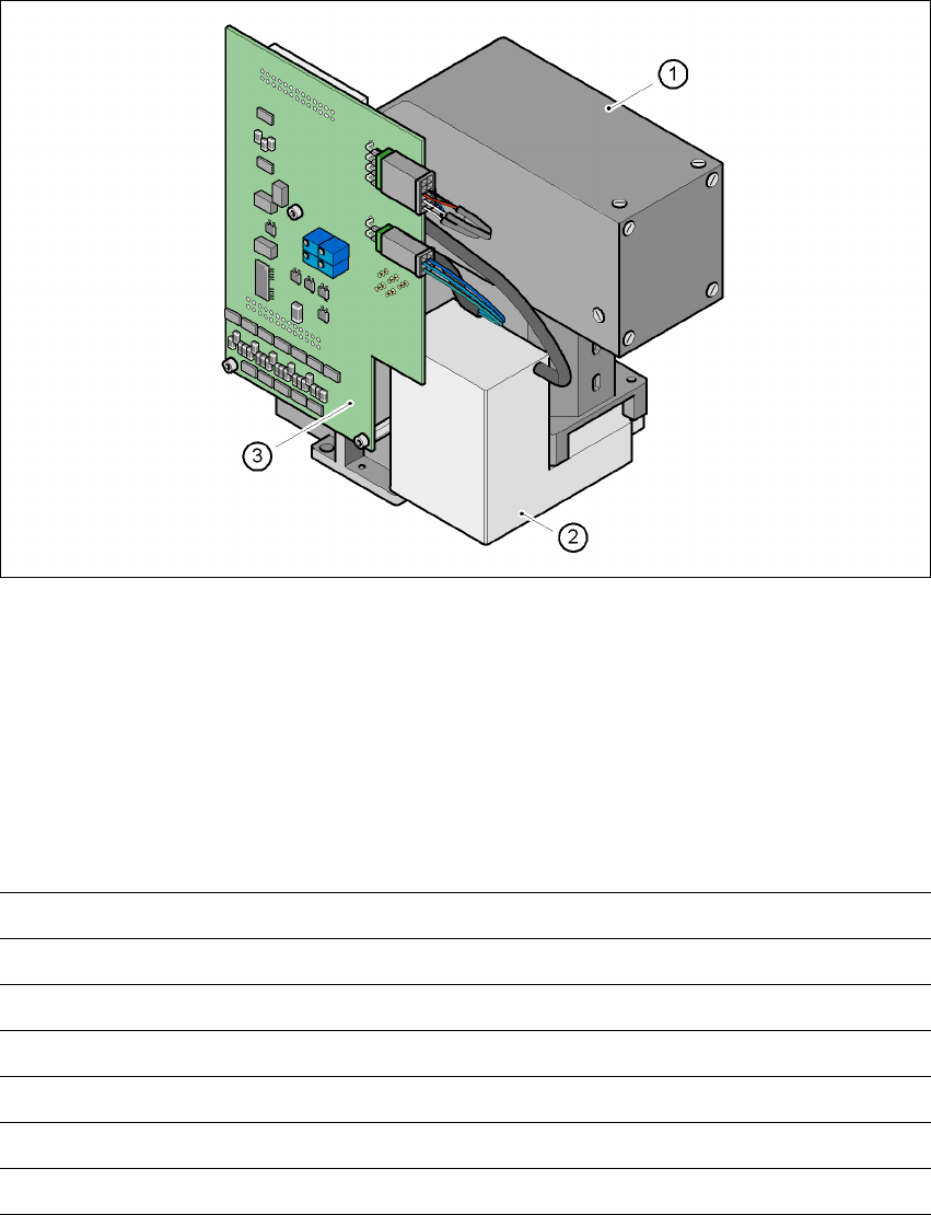
7.10 DCA vision camera
7.10.1 Structure
Fig. 7.10 - 1 DCA vision camera
7
(1) DCA vision camera, lens and illumination
(2) Camera amplifier
(3) Illumination control
7.10.2 Technical data - DCA vision camera
7
7
Component dimensions 0.6 x 0.3 mm² to 13 x 13 mm²
Range of components 0201 up to 13 x 13 mm², flip-chip, bare die
Min. lead pitch 0.4 mm
Min. bump pitch 0.2 mm
Min. ball/bump diameter 0.11 mm
Field of vision 15.6 x 15.6 mm²
Method of illumination Front lighting (four levels, programmable as required)
User Manual SIPLACE F5 HM 7 Options
Software Version SR.408.xx 03/2006 US Edition 7.10 DCA vision camera
211
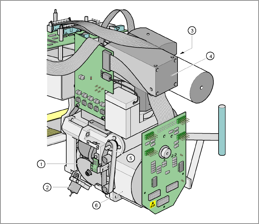
7.10.3 Structure of the 6-segment Collect& Place head with DCA vision camera
7
Fig. 7.10 - 2 Structure of the 6-segment Collect& Place head with DCA vision camera
7
(1) Star with 6 sleeves
(2) Motor for "Reject" valve adjustment drive
(3) Turning station
(4) DCA vision module
(5) Z axis drive
(6) Star motor