00194103-01.pdf - 第212页
7 Options User Manual SIP LACE F5 HM 7.10 DCA v ision camera Software Version SR.408.xx 03/2006 US Edition 212 7.10.4 Description of the 6 -segment Collect& Pla ce head with DCA vision camer a The 6-seg ment Colle ct…
User Manual SIPLACE F5 HM 7 Options
Software Version SR.408.xx 03/2006 US Edition 7.10 DCA vision camera
211
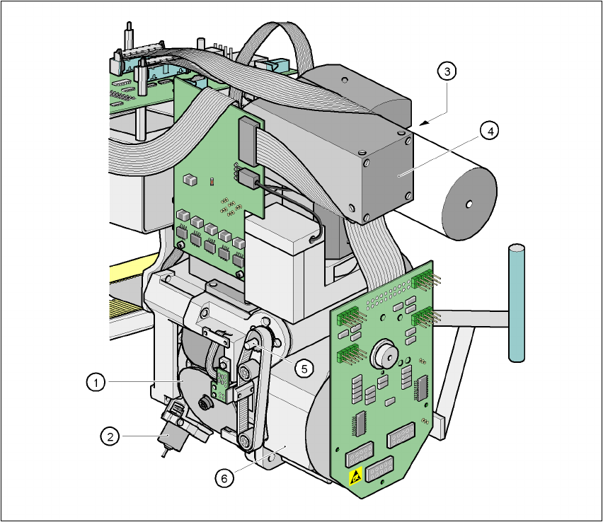
7.10.3 Structure of the 6-segment Collect& Place head with DCA vision camera
7
Fig. 7.10 - 2 Structure of the 6-segment Collect& Place head with DCA vision camera
7
(1) Star with 6 sleeves
(2) Motor for "Reject" valve adjustment drive
(3) Turning station
(4) DCA vision module
(5) Z axis drive
(6) Star motor

7 Options User Manual SIPLACE F5 HM
7.10 DCA vision camera Software Version SR.408.xx 03/2006 US Edition
212
7.10.4 Description of the 6-segment Collect& Place head with DCA vision camera
The 6-segment Collect&Place head can optically center and place components from 0.6 x 0.3
mm² to 13 x 13 mm² using the DCA vision module. The DCA package optimizes the speed and
accuracy when placing high-speed flip chips and bare die components. 7
7.10.5 Technical data for the 6-segment Collect&Place head with DCA camera
Range of components 0201 to 13 x 13 mm²
Component dimensions
max. height
max. weight
0.6 x 0.3 mm² to 13 x 13 mm²
8.5 mm
5 g
Min. lead pitch 0.4 mm
Min. bump pitch 0.2 mm
Min. ball/bump diameter 0.11 mm
Programmable set-down force 2.4 to 5.0 N
Max. placement rate 8,500 comp/h
Angular accuracy ± 0.225° / 3 σ, ± 0.30° / 4 σ, ± 0.45° / 6 σ
Placement accuracy ± 45 µm / 3 σ, ± 60 µm / 4 σ, ± 90 µm / 6 σ

User Manual SIPLACE F5 HM 7 Options
Software Version SR.408.xx 03/2006 US Edition 7.11 Fine calibration
213
7.11 Fine calibration
7.11.1 Overview
Fine calibration involves measuring the machine’s placement offset and determining the required
correction from this value. The ‘Fine calibration’ measuring program is integrated into the SIT-
EST program, and a detailed description of the measuring procedure is given in the ‘Fine calibra-
tion’ instructions (article no. 00191655-01).
CAUTION
The SITEST program is password-protected. It must only be called up and used by Siemens en-
gineers or appropriately trained personnel. 7
7.11.2 System requirements
The following system requirements must be fulfilled in order to use the fine calibration program:
Machine type F5HM
Station computer software version 406.xx or later
SITEST version 406.xx or later
7.11.3 Measuring equipment and tools
The following are supplied as standard:
– Mapping plate (glass plate in a metal frame)
– Double-sided transparent adhesive film
– Lighting unit
– Magazine for 48 glass components
– Magazine for 196 ceramic components
The following items must additionally be ordered:
– Waffle-pack tray holder to hold the magazine for the glass components and/or ceramic com-
ponents
The following parts may be ordered if required: