00194103-01.pdf - 第214页
7 Options User Manual SIP LACE F5 HM 7.11 Fine calibration S oftware Version SR .408.xx 03/2006 US E dition 214 – Mag azine for 4 8 glass compo nents – Magaz ine for 1 96 ceram ic compone nts 7.1 1.4 Description of the f…

User Manual SIPLACE F5 HM 7 Options
Software Version SR.408.xx 03/2006 US Edition 7.11 Fine calibration
213
7.11 Fine calibration
7.11.1 Overview
Fine calibration involves measuring the machine’s placement offset and determining the required
correction from this value. The ‘Fine calibration’ measuring program is integrated into the SIT-
EST program, and a detailed description of the measuring procedure is given in the ‘Fine calibra-
tion’ instructions (article no. 00191655-01).
CAUTION
The SITEST program is password-protected. It must only be called up and used by Siemens en-
gineers or appropriately trained personnel. 7
7.11.2 System requirements
The following system requirements must be fulfilled in order to use the fine calibration program:
Machine type F5HM
Station computer software version 406.xx or later
SITEST version 406.xx or later
7.11.3 Measuring equipment and tools
The following are supplied as standard:
– Mapping plate (glass plate in a metal frame)
– Double-sided transparent adhesive film
– Lighting unit
– Magazine for 48 glass components
– Magazine for 196 ceramic components
The following items must additionally be ordered:
– Waffle-pack tray holder to hold the magazine for the glass components and/or ceramic com-
ponents
The following parts may be ordered if required:
7 Options User Manual SIPLACE F5 HM
7.11 Fine calibration Software Version SR.408.xx 03/2006 US Edition
214
– Magazine for 48 glass components
– Magazine for 196 ceramic components
7.11.4 Description of the functions
First select the placement program for fine calibration. To do this, select the item ‘Cluster for fine
calibration’ via the ‘Options’ pull-down menu. Then process the mapping plate with the glass
components from a magazine on the waffle-pack tray holder.
After placement, start the SITEST program and start the ‘Fine calibration’ measuring program.
The placement head (Collect&Place head or Pick&Place head) will measure the current place-
ment positions of the glass and/or ceramic components and compare these positions with the cir-
cular fiducials on the mapping plate.
The offset values in the X and Y direction and the angular deviation are determined with the help
of the 48 glass components.
The reliability of the measurement results for the offset values is increased by using the 196 ce-
ramic components. Angular correction is not possible with ceramic components.
The offset values are used to calculate the corrected values, which are then entered in the
machine file.
User Manual SIPLACE F5 HM 7 Options
Software Version SR.408.xx 03/2006 US Edition 7.12 SIPLACE productivity lift
215
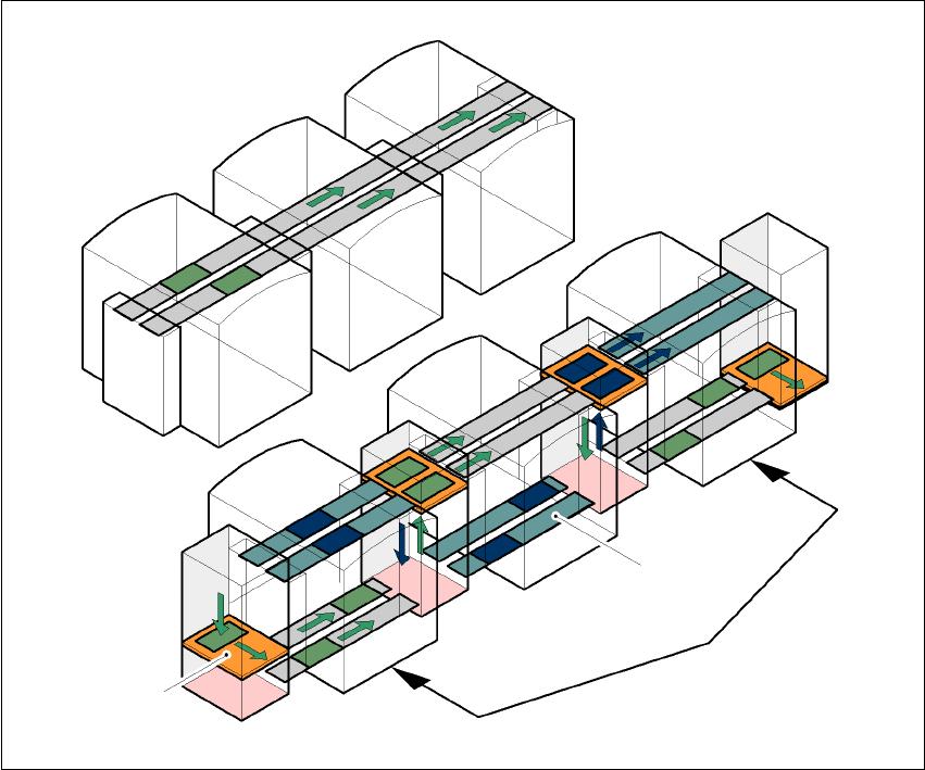
7.12 SIPLACE productivity lift
7.12.1 Concept of parallel placement
Placement lines are generally arranged in series and are linked to one another serially. The place-
ment program is processed sequentially while the PCBs are transported from one machine to the
next. This means that the placement of a PCB is distributed between various machines.
7
Fig. 7.12 - 1 A comparison of serial and parallel lines
When machines are connected in parallel, the components to be placed by individual machines
are combined. Several machines work through the same placement program. They place all the
components on one machine that would be distributed between several machines with serial pro-
cessing. When one machine runs out of capacity, the PCBs are moved to and placed at the next
machine with the same placement program. This combination of machines with the same compo-
nents to be placed is known as a group or “cluster”.
Serial line
Parallel line
Underfloor conveyor
Group (cluster)
Horizontal/
vertical lift