00194103-01.pdf - 第68页
2 Operational safety User Manual SIP LACE F5 HM 2.11 ESD guidelines S oftware Version SR.408.xx 03/2006 US Edition 68 Do not allo w modules with charge able and h ighly i nsulatin g materia ls to touch one another, e.g. …

User Manual SIPLACE F5 HM 2 Operational safety
Software Version SR.408.xx 03/2006 US Edition 2.11 ESD guidelines
67
2.11 ESD guidelines
2.11.1 What does ESD mean?
Almost all of the modules in use today are equipped with highly integrated MOS blocks and com-
ponents. The manufacturing techniques used mean that these electronic components are ex-
tremely sensitive to overvoltage and thus to electrostatic discharge. 2
The abbreviation for such electrostatically-sensitive groups of components is 'ESD'
(Electrostatic
S
ensitive Device). ’ESD’ is used internationally. 2
The following symbol on cabinet rating plates, racks or packaging indicates that components
which are sensitive to electrostatic discharge have been used and thus that the modules con-
cerned are also touch-sensitive. 2
ESDs can be destroyed by voltages and power levels that are far below the level
that can be perceived by humans. Such voltages occur if a person touches a com-
ponent or module without earthing themselves. Components that are exposed to
such overvoltages do not generally appear to be defective immediately - incorrect
behavior starts after the component or module has been in operation for some
time. 2
2.11.2 Important measures to protect against static charging
– Most plastics can easily become charged and must therefore be kept away from at-risk com-
ponents.
– Always ensure that people, the workplace and packaging are safely earthed when handling
electrostatic sensitive components.
2.11.3 Handling ESD modules
Do not touch electronic modules unless it is absolutely essential to do so in order to carry out other
work. If it is necessary, make sure that you do not touch the pins or printed conductors when you
pick up flat modules. 2
Do not touch components unless 2
– You are constantly earthed by an ESD wrist strap or
– You are wearing ESD shoes or ESD shoe earthing strips on an ESD floor.
Always discharge yourself before you touch an electronic module. To do this, simply touch a con-
ductive and earthed object immediately before you touch the module (such as unpainted parts of
a switch cabinet, a water pipe, etc.). 2
2 Operational safety User Manual SIPLACE F5 HM
2.11 ESD guidelines Software Version SR.408.xx 03/2006 US Edition
68
Do not allow modules with chargeable and highly insulating materials to touch one another, e.g.
plastic films, insulating table surfaces or items of clothing made from synthetic fibers. 2
Always place the modules on a conductive surface (table with an ESD coating, conductive ESD
foam, ESD bag or container). 2
Do not bring modules near visual display units, monitors or televisions. Keep them at least 10 cm
away from the screen. 2
2.11.4 Measurements and modifications to ESD modules
Do not take measurements on such modules unless 2
– the measuring device is earthed (e.g. via PE conductors) or
– you discharge the measuring head just before taking measurements with a potential-free mea-
suring device (e.g. by touching an unpainted metal part of the controller casing).
Æ Always use an earthed soldering iron if you carry out any soldering work.
2.11.5 Dispatching ESD modules
Always store modules and components in conductive packaging (e.g. metallized plastic bags or
metal sleeves) and dispatch them in conductive packaging. 2
If the packaging is not conductive, place the modules in a conductive envelope before packaging.
Use conductive expanded rubber, ESD bags, domestic aluminum foil or paper, for example.
NEVER use plastic bags or film. 2
If the module has integral batteries, ensure that the conductive packaging does not touch or short-
circuit the battery terminals and, if necessary, first cover the terminals with insulating tape or ma-
terial. 2
2
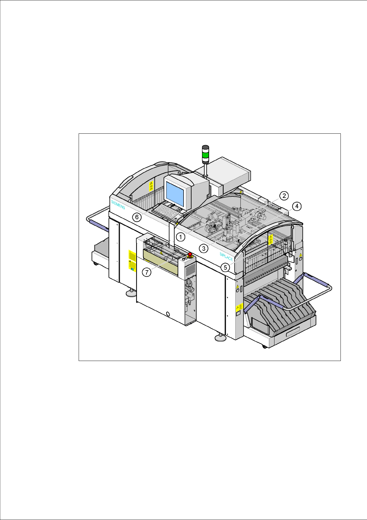
User Manual SIPLACE F5 HM 3 Technical data
Software Version SR.408.xx 03/2006 US Edition 3.1 Description of the machine
69
3 Technical data
3.1 Description of the machine
The placement machine is a high-performance placement system with one gantry. It holds a 6/
12-segment Collect&Place head, a Pick&Place head and a PCB camera.
3
Fig. 3.1 - 1 Overall view of the placement system
(1) 6/12-segment Collect&Place head with component camera
(2) Gantry 1 with PCB camera
(3) Pick&Place head
(4) Fine-pitch vision camera for the Pick&Place head
(5) Stationary component supply (location 1)
(6) Stationary component supply (location 3)
(7) PCB conveyor (dual conveyor option)