00194103-01.pdf - 第69页
User Manual SIPLAC E F5 HM 3 Technical data Software Vers ion SR.408.xx 03/2006 U S Edition 3.1 Descript ion of the machine 69 3 T echnical dat a 3.1 Description of the machine The pla cement ma chine is a h igh-per form…
2 Operational safety User Manual SIPLACE F5 HM
2.11 ESD guidelines Software Version SR.408.xx 03/2006 US Edition
68
Do not allow modules with chargeable and highly insulating materials to touch one another, e.g.
plastic films, insulating table surfaces or items of clothing made from synthetic fibers. 2
Always place the modules on a conductive surface (table with an ESD coating, conductive ESD
foam, ESD bag or container). 2
Do not bring modules near visual display units, monitors or televisions. Keep them at least 10 cm
away from the screen. 2
2.11.4 Measurements and modifications to ESD modules
Do not take measurements on such modules unless 2
– the measuring device is earthed (e.g. via PE conductors) or
– you discharge the measuring head just before taking measurements with a potential-free mea-
suring device (e.g. by touching an unpainted metal part of the controller casing).
Æ Always use an earthed soldering iron if you carry out any soldering work.
2.11.5 Dispatching ESD modules
Always store modules and components in conductive packaging (e.g. metallized plastic bags or
metal sleeves) and dispatch them in conductive packaging. 2
If the packaging is not conductive, place the modules in a conductive envelope before packaging.
Use conductive expanded rubber, ESD bags, domestic aluminum foil or paper, for example.
NEVER use plastic bags or film. 2
If the module has integral batteries, ensure that the conductive packaging does not touch or short-
circuit the battery terminals and, if necessary, first cover the terminals with insulating tape or ma-
terial. 2
2
User Manual SIPLACE F5 HM 3 Technical data
Software Version SR.408.xx 03/2006 US Edition 3.1 Description of the machine
69
3 Technical data
3.1 Description of the machine
The placement machine is a high-performance placement system with one gantry. It holds a 6/
12-segment Collect&Place head, a Pick&Place head and a PCB camera.
3
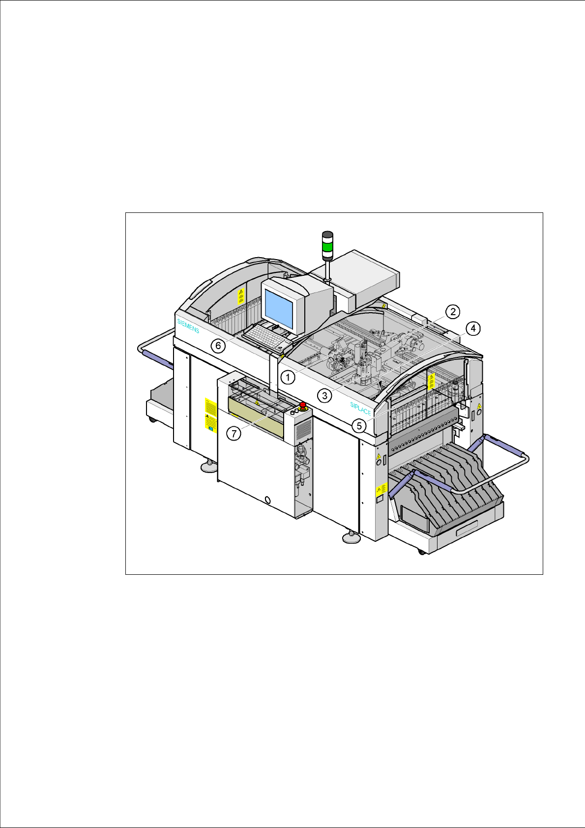
Fig. 3.1 - 1 Overall view of the placement system
(1) 6/12-segment Collect&Place head with component camera
(2) Gantry 1 with PCB camera
(3) Pick&Place head
(4) Fine-pitch vision camera for the Pick&Place head
(5) Stationary component supply (location 1)
(6) Stationary component supply (location 3)
(7) PCB conveyor (dual conveyor option)
3 Technical data User Manual SIPLACE F5 HM
3.1 Description of the machine Software Version SR.408.xx 03/2006 US Edition
70
The placement heads pick up components from stationary feeders and use them to populate the
PCB clamped on the PCB conveyor.
The 12-segment Collect&Place head can process size 0201 to 18.7 mm x 18.7 mm components.
The 6-segment Collect&Place head can raise the placement rate when there is a high proportion
of ICs in the placement process. The component sizes range from 0603 to 32 x 32 mm². Even
smaller components can be placed such as 0201 when using the DCA and 0201 packages.
The Pick&Place head is particularly suitable for placing fine pitch components. It places compo-
nent sizes ranging from 1.6 x 0.8 mm² to 55 x 55 mm². In addition to the PCB centering vision
module, the placement machine also has component vision modules for the Collect&Place head
and Pick&Place head.
The concept behind the automatic placement system
– with its stationary feeders,
– PCBs that do not move during placement
– and positionable placement heads
has a number of significant benefits:
– For example, the flexible 6/12-segment Collect&Place heads combined with automatic nozzle
changer enables the nozzle configuration to be changed temporarily and automatically
adapted to receive different component sizes. The same applies to the Pick&Place head. You
can also optimize the traversing paths and the placement sequence.
– With stationary feeders, even the tiniest components are picked up reliably.
– The components cannot slip on the PCB during placement (as is often the case with moving
PCBs) since the PCB does not move.
– Sophisticated optical centering systems (vision modules) for components and PCBs also en-
sure high component positioning accuracy.
– Components can be topped up and tapes can be spliced without stopping the machine.
– Prepared component trolleys enable the placement system to be retooled without long stop-
pages.
A waffle-pack changer may be used to supply components.