00194103-01.pdf - 第93页
User Manual SIPLAC E F5 HM 3 Technical data Software Vers ion SR.408.xx 03/2006 U S Edition 3.9 Placem ent heads 93 3.9.8 Descripti on of the Pick&Pl ace head The Pick & Plac e head wor ks on the Pick&Plac e …
3 Technical data User Manual SIPLACE F5 HM
3.9 Placement heads Software Version SR.408.xx 03/2006 US Edition
92
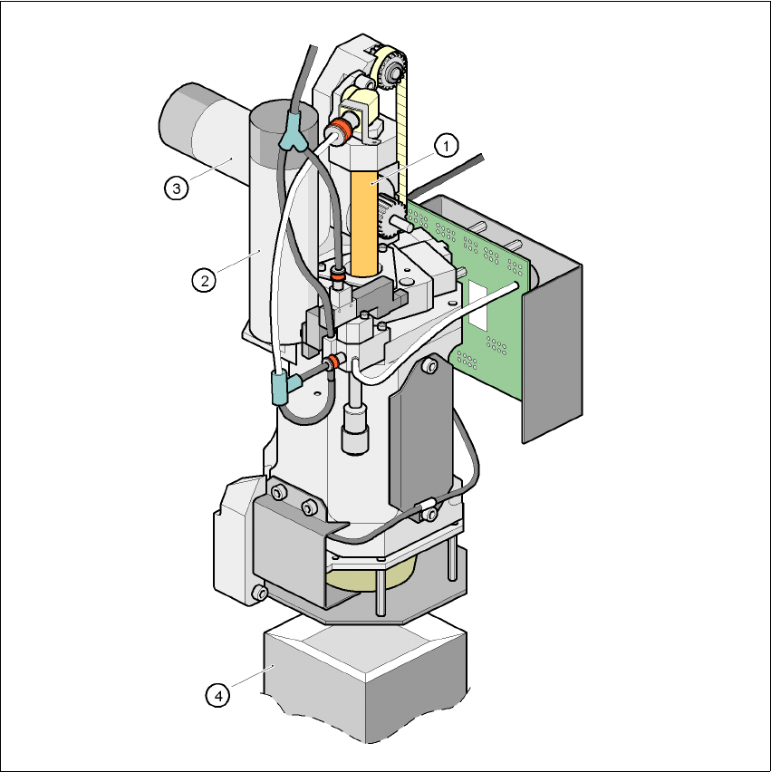
3.9.7 Structure of the Pick&Place head
3
Fig. 3.9 - 3 Structure of the Pick&Place head
(1) Sleeve
(2) DR axis drive
(3) Z axis drive
(4) Fine-pitch vision module

User Manual SIPLACE F5 HM 3 Technical data
Software Version SR.408.xx 03/2006 US Edition 3.9 Placement heads
93
3.9.8 Description of the Pick&Place head
The Pick & Place head works on the Pick&Place principle. According to this principle, a compo-
nent is picked up by the nozzle with the aid of a vacuum. It is then optically centered by the fine-
pitch or flip-chip vision module, turned in the placement angle and placed on the PCB with high
precision. The Pick&Place head offers particularly high angular accuracy. 3
3.9.9 Technical data - Pick&Place head
3
Range of components 1.6 x 0.8 mm² up to 55 x 55 mm² (fine-pitch vision module)
1.0 x 1.0 mm² up to 20 x 20 mm² (flip-chip vision module)
Max. height Component height ≤ 13.5mm- PCB thickness
- PCB warpage
Option:
Component height ≤ 20mm- PCB thickness
- PCB warpage
Min. lead pitch 0.4 mm (fine-pitch vision module)
0.25 mm (flip-chip vision module)
Min. bump pitch 0.56 mm (fine-pitch vision module)
0.14 mm (flip-chip vision module)
Min. ball/bump diameter 0.32 mm (fine-pitch vision module)
0.08 mm (flip-chip vision module)
Max. dimensions up to 32 x 32 mm² with single measurement
up to 55 x 55 mm² with quadruple measurement
Max. weight 25 g
Programmable set-down force 1 - 10 N
Nozzle types 4xx, 5 standard nozzles and flip-chip nozzle with nozzle changer
Component centering Fine-pitch vision module (standard)
Flip-chip vision module, option (see Section 7.8
, page 202)
Placement rate 1,800 comp/h
D axis resolution 0.005°
Angular accuracy ± 0.053° / 3 σ, ± 0.07° / 4 σ, ± 0.105° / 6 σ
Placement accuracy Fine-pitch vision module:
± 37.5 µm / 3 σ, ± 50 µm / 4 σ, ± 75 µm / 6 σ
Flip-chip vision module:
± 30.0 µm / 3 σ, ± 40 µm / 4 σ, ± 60 µm / 6 σ

3 Technical data User Manual SIPLACE F5 HM
3.10 Vision modules Software Version SR.408.xx 03/2006 US Edition
94
3.10 Vision modules
Each placement system has 3
– one component vision module on the Collect&Place head,
– one fine-pitch vision module on the machine frame and
– one PCB vision module on the underside of the X axis gantry.
3
The vision analysis unit is located in the control unit for the placement system. The component
vision module is used to determine: 3
– the precise position of the components at the nozzle and
– the geometry of the package form.
3
The PCB vision module uses fiducials on the PCBs to determine: 3
– the position of the PCB,
– its rotation angle
– and the PCB skew.
Defective PCBs or subpanels will be marked with ink spots. The PCB vision module scans the
ink spots and signals that these circuits shall not be assembled. 3
The PCB vision module also uses fiducials on the feeders to determine the exact pick-up position
of components. This is particularly important for small components. 3
3.10.1 Technical data - Component vision module on the 12-segment
Collect&Place head
3
Max. component dimensions 0.6 x 0.3 mm² to 18.7 x 18.7 mm²
Component range 0201 to PLCC44
including BGA, µBGA, flip-chip, TSOP, QFP
PLCC, SO to SO32, DRAM
Min. lead pitch 0.5 mm
Field of vision 24 x 24 mm²
Method of illumination Front lighting (three levels, programmable as re-
quired)