00194103-01.pdf - 第95页
User Manual SIPLAC E F5 HM 3 Technical data Software Vers ion SR.408.xx 03/2006 U S Edition 3.10 V ision modules 95 3.10.2 T echnical dat a - S t andard component visi on module on the 6-segm ent C &P head 3 3 3.10.3…

3 Technical data User Manual SIPLACE F5 HM
3.10 Vision modules Software Version SR.408.xx 03/2006 US Edition
94
3.10 Vision modules
Each placement system has 3
– one component vision module on the Collect&Place head,
– one fine-pitch vision module on the machine frame and
– one PCB vision module on the underside of the X axis gantry.
3
The vision analysis unit is located in the control unit for the placement system. The component
vision module is used to determine: 3
– the precise position of the components at the nozzle and
– the geometry of the package form.
3
The PCB vision module uses fiducials on the PCBs to determine: 3
– the position of the PCB,
– its rotation angle
– and the PCB skew.
Defective PCBs or subpanels will be marked with ink spots. The PCB vision module scans the
ink spots and signals that these circuits shall not be assembled. 3
The PCB vision module also uses fiducials on the feeders to determine the exact pick-up position
of components. This is particularly important for small components. 3
3.10.1 Technical data - Component vision module on the 12-segment
Collect&Place head
3
Max. component dimensions 0.6 x 0.3 mm² to 18.7 x 18.7 mm²
Component range 0201 to PLCC44
including BGA, µBGA, flip-chip, TSOP, QFP
PLCC, SO to SO32, DRAM
Min. lead pitch 0.5 mm
Field of vision 24 x 24 mm²
Method of illumination Front lighting (three levels, programmable as re-
quired)

User Manual SIPLACE F5 HM 3 Technical data
Software Version SR.408.xx 03/2006 US Edition 3.10 Vision modules
95
3.10.2 Technical data - Standard component vision module on the
6-segment C&P head
3
3
3.10.3 Technical data - Fine-pitch vision module
3.10.4 Technical data - PCB vision module
Component dimensions 1.6 x 0.8 mm² up to 32 x 32 mm²
Component range 0603 to 32x32mm²
PLCC, SO, QFP, TSDP, SOT, MELF, CHIP, IC BGA
Min. lead pitch 0.5 mm
Field of vision 24 x 24 mm²
Method of illumination Front lighting (three levels, programmable as required)
Max. component size 32 x 32 mm² (single measuremen)
55 x 55 mm² (multiple measurement)
(larger components possible on request)
Component range PLCC, LCCC, QFP, SO, BGA, flip-chip,
components with connectors up to 55 x 55 mm²
(J leads and gull-wings, balls, bumps)
Min. lead pitch 0.4 mm
Field of vision 38 x 38 mm²
Method of illumination Front lighting (three levels, programmable as required)
Fiducials up to 3 per placement program
Local fiducials up to 2 per PCB (may be of different types)
Library size up to 255 fiducial types - system fiducials ≥ 249
Image analysis Correlation principle based on grayscale values
Method of illumination Front-lighting
Detection time per fiducial/bad fidu-
cial
0.4 s
Field of vision 5.7 x 5.7 mm²
3 Technical data User Manual SIPLACE F5 HM
3.11 PCB single conveyor Software Version SR.408.xx 03/2006 US Edition
96
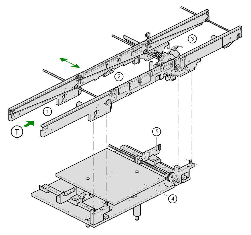
3.11 PCB single conveyor
3.11.1 Structure
The placement system is supplied with a single conveyor as standard. A dual conveyor is avail-
able as an option. The left or the right side of the PCB conveyor can be used as the stationary
side, as required. 3
3
Fig. 3.11 - 1 Structure of the PCB single conveyor
(1) Input conveyor (2) Center conveyor
(3) Output conveyor (4) Lifting table
(5) Width adjustment T Direction of PCB transport 3